A droplet falling onto a solid, dry surface seems like a simple situation, one that would be easy to understand. But splashes can be unpredictable. Velocity, viscosity, and surface tension all play clear roles, but the surrounding air also has an impact – drop the air pressure low enough and a droplet won’t splash. A new paper has tackled the problem, producing a mathematical model in agreement with experimental results. So why do some drops splash and others don’t? When a drop falls, its momentum flattens it into a pancake shape while surface tension struggles to hold it together. The spreading edge, called the lamella, can pull away from the surface. When it does, a pocket of high pressure forms beneath it due to lubrication effects, and the faster airflow over the top of the lamella creates a suction effect. This is analogous to a wing producing lift. Like the momentum that spread the droplet, the lift force pulls the lamella and ejecta sheet further up and outward, overcoming the restoring force of surface tension and tearing the droplet apart. For more on the effect, check out the research paper or this Inside Science article. (Video credit: G. Riboux and J. Gordillo; via Inside Science)
Search results for: “lift”
Reader Question: Winglets
Reader tvargo writes:
First off… love your blog! I know very little about physics, but love reading about it. Could you potentially explain what the little upturned ends of wings do? looking on wikipedia is see this: “There are several types of wingtip devices, and although they function in different manners, the intended effect is always to reduce the aircraft’s drag by partial recovery of the tip vortex energy.” huh?
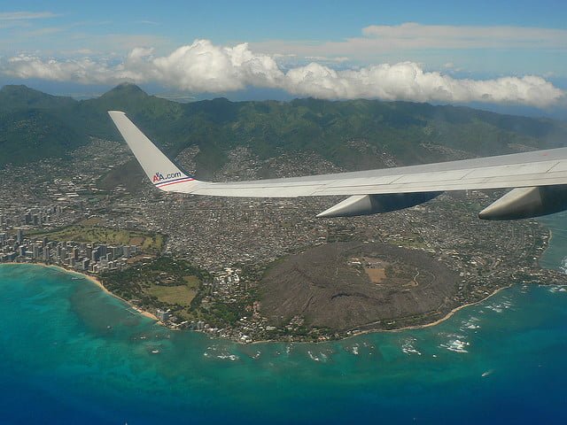
Thanks! That’s a great question. Winglets are very common, especially on commercial airliners. To understand what they do, it’s helpful to first think about a winglet-less airplane wing. Each section of the wing produces lift. For a uniform, infinite wing, the lift produced at each spanwise location would be the same. In reality, though, wings are finite and wingtip vortices at their ends distort the flow. The vortices’ upward flow around the ends of the wing reduces the lift produced at the wing’s outermost sections, making the finite wing less efficient (though obviously more practical) than an infinite wing.
Adding a winglet modifies the end conditions, both by redirecting the wingtip vortices away from the underside of the wing and by reducing the strength of the vortex. Both actions cause the winglet-equipped wing to produce more lift near the outboard ends than a wing without winglets.
But why, you might ask, does the Wikipedia explanation talk about reducing drag? Since a finite wing produces less lift than an infinite one, finite wings must be flown at a higher angle of attack to produce equivalent lift. Increasing the angle of attack also increases drag on the wing. (If you’ve ever stuck a tilted hand out a car window at speed, then you’re familiar with this effect.) Because the winglet recovers some of the lift that would otherwise be lost, it allows the wing to be flown at a lower angle of attack, thereby reducing the drag. Thus, overall, adding winglets improves a wing’s efficiency. (Photo credit: C. Castro)

4th Birthday: Wingtip Vortices


Wingtip vortices are a result of the finite length of a wing. Airplanes generate lift by having low-pressure air travelling over the top of the wing and higher pressure air along the bottom. If the wing were infinite, the two flows would remain separate. Instead, the high-pressure air from under the wing sneaks around the wingtip to reach the lower pressure region. This creates the vorticity that trails behind the aircraft. I was first introduced to the concept of wingtip vortices in my junior year during introductory fluid dynamics. As I recall, the concept was utterly bizarre and so difficult to wrap our heads around that everyone, including the TA, had trouble figuring out which way the vortices were supposed to spin. A few good photos and videos would have helped, I’m sure. (Photo credits: U.S. Coast Guard, S. Morris, Nat. Geo/BBC2)

Hummingbird Hovering
The hummingbird has long been admired for its ability to hover in flight. The key to this behavior is the bird’s capability to produce lift on both its downstroke and its upstroke. The animation above shows a simulation of hovering hummingbird. The kinematics of the bird’s flapping–the figure-8 motion and the twist of the wings through each cycle–are based on high-speed video of actual hummingbirds. These data were then used to construct a digital model of a hummingbird, about which scientists simulated airflow. About 70% of the lift each cycle is generated by the downstroke, much of it coming from the leading-edge vortex that develops on the wing. The remainder of the lift is creating during the upstroke as the bird pulls its wings back. During this part of the cycle, the flexible hummingbird twists its wings to a very high angle of attack, which is necessary to generate and maintain a leading-edge vortex on the upstroke. The full-scale animation is here. (Image credit: J. Song et al.; via Wired; submitted by averagegrdy)

The Magnus Effect in Football
Like many sports, the gameplay in football can be strongly affected by the ball’s spin. Corner kicks and free kicks can curve in non-intuitive ways, making the job of the goalie much harder. These seemingly impossible changes in trajectory are due to airflow around the spinning ball and what’s known as the Magnus effect. In the animation above, flow is moving from right to left around a football. As the ball starts spinning, the symmetry of the flow around the ball is broken. On top, the ball is spinning toward the incoming flow, and the green dye pulls away from the surface. This is flow separation and creates a high-pressure, low-velocity area along the top of the ball. In contrast, the bottom edge of the ball pulls dye along with it, keeping flow attached to the ball for longer and creating low pressure. Just as a wing has lift due to the pressure difference on either side of the wing, the pressure imbalance on the football creates a force acting from high-to-low pressure. In this case, that is a downward force relative to the ball’s rightward motion. In a freely moving football, this force would curve its trajectory to the side. (GIF credit: SkunkBear/NPR; original video: NASA Ames; via skunkbear)
Turbojet Engines
[original media no longer available]
GE has a great new video with a straightforward explanation of the turbojet and the turbofan engines. The simplest description of the engines–suck, squeeze, bang, blow–sounds like a euphemism but it’s fairly accurate. The engines draw in air, compress it by making it flow through a series of small rotating blades, add fuel and combust the mixture, pull out energy through a turbine, and then blow the high-speed exhaust out the back to generate thrust. The thrust is key because it’s the force that overcomes drag on the plane and also generates the speed needed to create lift. There are two ways to significantly increase thrust: a) increase the mass flow rate of air through the engine, and/or b) increase the exhaust velocity. The turbojet engine draws in smaller amounts of air but generates very high exhaust velocities. The turbofan is today’s preferred commercial aircraft engine because it can generate thrust more efficiently at the desired aircraft velocity. The turbofan essentially has a turbojet engine in its center and is surrounded by a large air-bypass. Most of the air passing through the engine flows through the bypass and the fan. This increases its velocity only slightly, but it means that the engine accelerates much larger amounts of air without requiring much larger amounts of fuel. As an added bonus, the lower exhaust velocities of the turbofan engine make it much quieter in operation. (Video credit: General Electric)
Wing-Warping
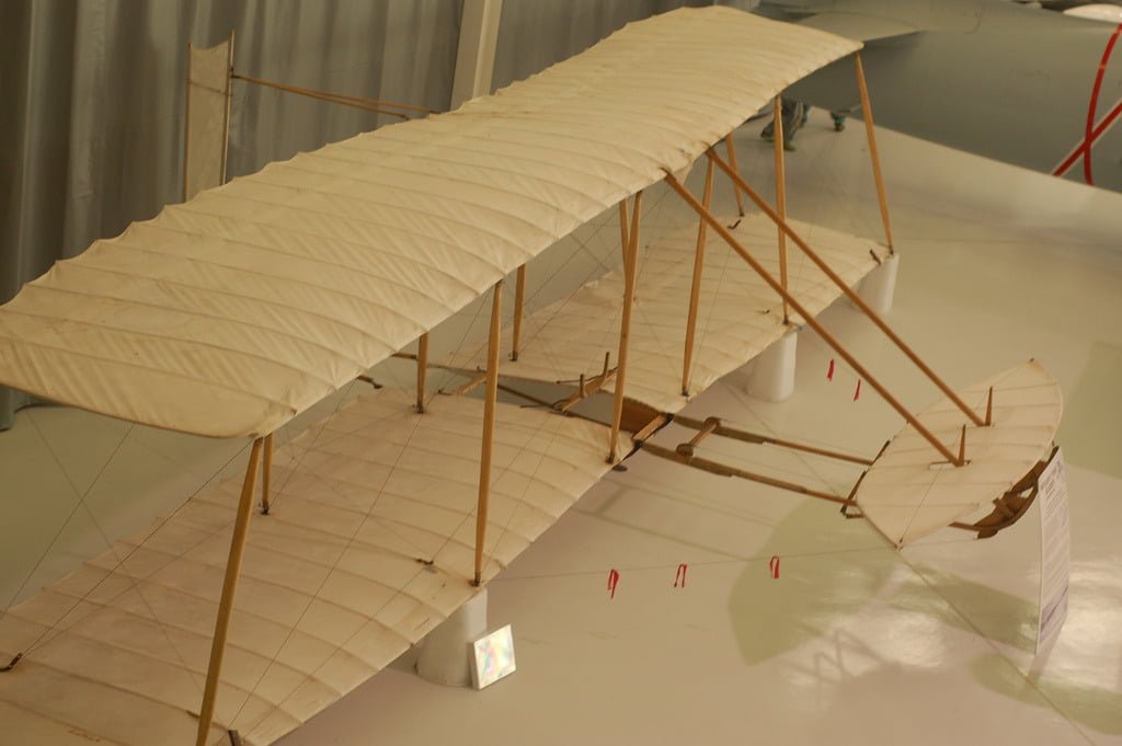
This replica of the Wright brothers’ 1902 glider demonstrates one of the important innovations the brothers contributed toward powered heavier-than-air flight. To control an aircraft in roll, the Wright brothers developed the idea of wing-warping. The pilot would lie in the cradle (center of image) and shift his body to one side. A system of wires and pulleys would then twist the wings from their rear edge, pulling one side down and the other up. This deflection is akin to changing the wing’s angle of attack. Deflecting the right wingtip downward increased the lift on the right side of the glider, while simultaneously the upward deflection on the left decreased the lift on that side. This causes the glider to bank, or roll, with the right wing up, thereby generating a leftward turn. The lift differential also caused a drag differential, though, with increased drag on the lifted (right, in this case) wing. That extra drag tended to pull the aircraft’s nose rightward, a condition known as adverse yaw. To counter it, the Wright brothers installed a steerable rudder and linked it to the wing-warping mechanism, allowing them to turn with much less effort than other conventional craft. Although wing-warping has been replaced with ailerons, the control principles remain the same. For more, watch this demo of the wing warping mechanism on a 1903 Wright Flyer replica. (Image credit: C. Devers)

Separating Flow
Flow separation occurs when a fluid is unable to flow smoothly around an object. In the case of the photo above, fog is being used to visualize flow around an airfoil at a large negative angle of attack. The incoming flow stagnates at a point on top of the airfoil, and streamlines on either side of that point split to move around the airfoil. Those on top are accelerated to high velocity, generating smooth, low-pressure flow over the aft section of the upper surface. On the other side of the stagnation point, however, the fog is trying to flow around the curve of the leading edge but the local pressure gradient is increasing, which slows the flow. Ultimately, it separates from the airfoil, creating a large region of recirculating, turbulent flow. When this effect occurs on the upper surface of a wing at a high (positive) angle of attack, it is called stall and causes a dramatic loss in lift. (Photo credit: Wikimedia/Smart Blade GmbH)
Viscous Fingers
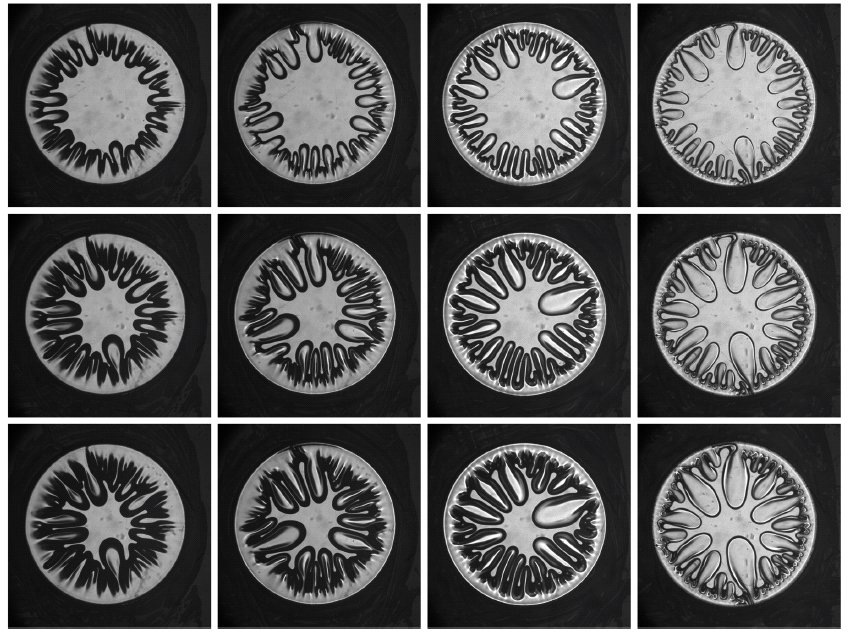
Viscous liquid placed between two plates forms a finger-like instability when the top plate is lifted. The photos above show the evolution of the instability for four initial cases (top row, each column) in which the initial gap between the plates differs. Each row shows a subsequent time during the lifting process. As the plate is pulled up, the viscous liquid adheres to it and air from the surroundings is entrained inward to replace the fluid. This forms patterns similar to the classic Saffman-Taylor instability caused when less viscous fluid is injected into a more viscous one. (Photo credit: J. Nase et al.)

Tiny Fliers
There’s an apocryphal story claiming that, aerodynamically speaking, honeybees should not be able to fly. Obviously, they can, but it’s true that a small, flapping creature and a large, fixed-wing aircraft will not generate lift exactly the same way. NYU professor Leif Ristroph has a lot of projects exploring flapping flight on smaller scales, as seen in this video. His oscillatory fliers and rotating flapping flight simulator have both been featured previously. Part of the beauty of these projects is their size; in a field that’s historically required giant wind tunnels and room-length wave tanks, Ristroph’s work provides insight into long-standing problems using apparatuses that fit on a countertop. (Video credit: Cool Hunting/L. Ristroph et al.)
.svg)
.svg)