Tag: stall

  • Flow on Commercial Wings

    Flow on Commercial Wings

    Even in an era of supercomputers, there is a place for quick and dirty methods of flow visualization. Here we see a model of a swept wing like those seen on many commercial airliners. It was painted with a layer of fluorescent oil, then placed in a wind tunnel and subjected to flow. As air blows across the model, it moves the oil, leaving behind streaks that show how air near the surface moves. 

    We can see, for example, that near the fuselage, the air flows mostly front to back across the wing. That’s what we expect, especially for a wing generating lift. But further out on the wing, the flow moves mostly along the wing, not across it. There’s also a distinctive line running just a short ways behind the leading edge on this outer section of wing. It looks as though air flowing over the wing separated at this point, leaving disordered and unhelpful flow behind. It’s likely that the model was tested at an angle of attack where the outer section of the wing was beginning to stall. (Image credit: ARA)

  • Featured Video Play Icon

    Why Do Backwards Wings Exist?

    Over the years, there have been many odd airplane designs, but one you probably haven’t seen much is the forward-swept wing. While most early aircraft featured straight wings, rear-swept wings are fairly common today, especially among commercial airliners. A rear-swept wing has its forward-most point at the root of the ring, where it attaches to the fuselage. The sweep breaks up the incoming flow into a chordwise component that flows from the leading edge to the trailing edge of the wing and a spanwise component that flows along the wing. Compared to straight wings, a swept wing provides better stability and control when flying at transonic speeds where shock waves can form on the wing (even though the plane itself is not supersonic).

    The trouble with rear-swept wings is that when they stall, they do so from the wingtips inward. Since the ailerons that control the plane’s orientation are out near the wingtips, that’s a problem. Forward-swept wings were supposed to solve this issue because they would stall from the root outward. But they came with a whole new set of problems, which included the need for robust onboard computers controlling them constantly to keep them in stable flight. In the end, the disadvantages outweighed any gains and so, for the most part, the forward-swept wing design has seen little flight time. (Image and video credit: Real Engineering)

  • Delta Wing Flow Viz

    Delta Wing Flow Viz

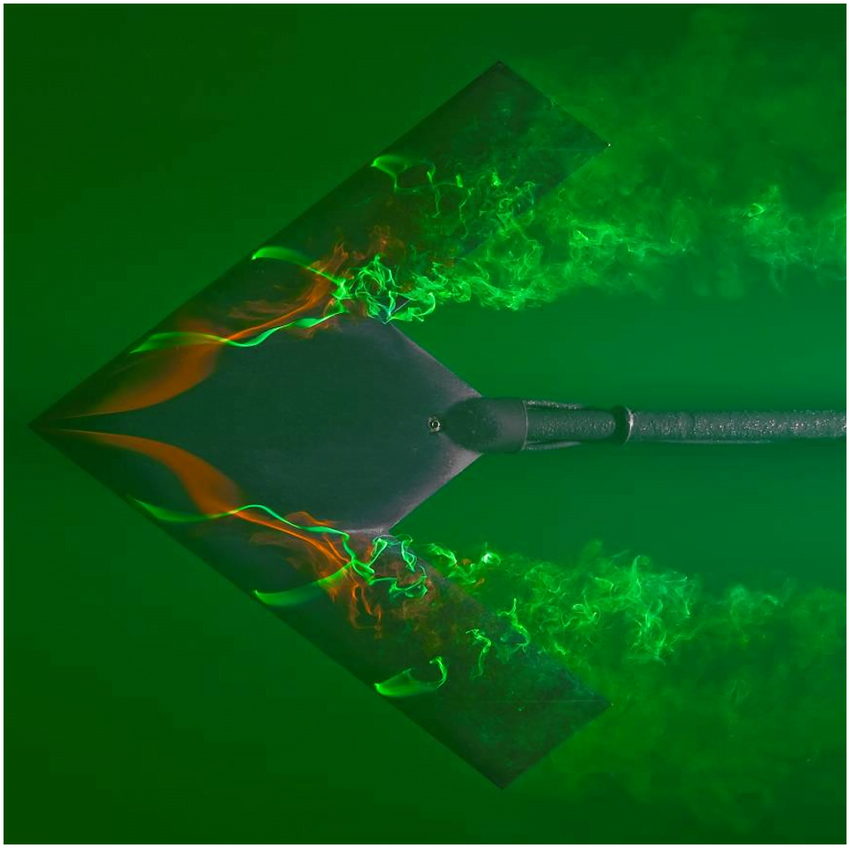
    Designing new aerodynamic vehicles typically requires a combination of multiple experimental and numerical techniques. The photo above shows a model for an unmanned flying wing-type vehicle. Here it’s tested in a water tunnel with dye introduced to the flow to highlight different areas. The model is at a high angle of attack (18 degrees) relative to the oncoming flow. This puts it in danger of flow separation and stall, the point where a wing experiences a drastic loss in lift. The smooth flow over the front of the model indicates it hasn’t reached this point yet, but notice how both the green and red dyes are separating from the model and becoming very turbulent over the back of the wing. If the model were pushed to an even higher angle of attack, that separation point would move further forward, bringing stall that much closer. (Image credit: L. Erm and J. Drobik; research credit: R. Cummings and A. Schütte)

  • Featured Video Play Icon

    Living Fluid Dynamics

    This short film for the 2016 Gallery of Fluid Motion features Montana State University students experiencing fluid dynamics in the classroom and in their daily lives. As in her previous film (which we deconstructed), Shanon Reckinger aims to illustrate some of our everyday interactions with fluids. This time identifying individual phenomena is left as an exercise for the viewer, but there are hints hidden in the classroom scenes. How many can you catch? I’ve labeled some of the ones I noticed in the tags. (Video credit: S. Reckinger et al.)

  • Plasma Flow Control

    Plasma Flow Control

    Engineers frequently face the challenge of maintaining control of air flow around an object across a wide range of conditions. After all, wind turbines and airplanes don’t always get to choose the perfect weather. To widen their operating ranges, designers can use active flow control to keep air flowing around an airfoil instead of separating and causing stall. One method of flow control uses plasma actuators on the upper surface of an airfoil. When activated, the plasma actuator ionizes air near the wing surface, producing the purplish glow seen above. That ionized air, or plasma, gets accelerated by the electric field of the device. The acceleration adds momentum to air near the wing surface, which helps it stay attached and flowing smoothly despite the unfavorable pressure conditions near the trailing edge of the wing. Compared to other methods of active flow control, plasma actuation is relatively simple to implement and so is actively being researched for applications in aviation and wind energy. (Image and research credit: I. Brownstein et al., source)

  • Featured Video Play Icon

    Perching Physics

    Compared to birds, manmade aircraft tend to be quite limited and inelegant. Fixed-wing aircraft, for example, require long, flat areas for take-off and landing, whereas birds of all sizes are adept at maneuvers like perching. This video examines the perching behaviors of large birds and extends the physics to a small unmanned aerial vehicle (UAV). As a bird approaches a perching location, it pitches its body and wings upward. This places the bird in what’s known as deep stall, where air flowing over the upper surface of the wing separates just after the leading edge. This move dramatically increases drag on the bird, slowing it for landing. At the same time, the speed of the pitch maneuver generates a vortex on the wing that helps the bird maintain lift despite the drop in speed. With the help of both forces, the bird can make a graceful, controlled landing in only a short distance. (Video credit: J. Mitchell et. al.)

  • Laser-Induced Fluorescence

    Laser-Induced Fluorescence

    One of the challenges of experimental fluid dynamics is capturing information about a flow that varies in three spatial dimensions and time. Experimentalists have developed many techniques over the years–some qualitative and some quantitative–all of which can only capture a small portion of the flow. The photos above are a series of laser-induced fluorescence (LIF) images of an airfoil at increasing angles of attack. The green swirls are from an added chemical that fluoresces after being excited with a laser. In this case, the technique is providing flow visualization, showing how flow over the upper surface of the airfoil shifts and separates as the angle of attack increases. The technique can also be used, however, to measure velocity, temperature, and chemical concentration. (Image credit: S. Wang et al.)

  • Separating Flow

    Separating Flow

    Flow separation occurs when a fluid is unable to flow smoothly around an object. In the case of the photo above, fog is being used to visualize flow around an airfoil at a large negative angle of attack. The incoming flow stagnates at a point on top of the airfoil, and streamlines on either side of that point split to move around the airfoil. Those on top are accelerated to high velocity, generating smooth, low-pressure flow over the aft section of the upper surface. On the other side of the stagnation point, however, the fog is trying to flow around the curve of the leading edge but the local pressure gradient is increasing, which slows the flow. Ultimately, it separates from the airfoil, creating a large region of recirculating, turbulent flow. When this effect occurs on the upper surface of a wing at a high (positive) angle of attack, it is called stall and causes a dramatic loss in lift.  (Photo credit: Wikimedia/Smart Blade GmbH)

  • Dynamic Stall

    Dynamic Stall

    In nature, birds and other flying animals often use unsteady flow effects to enhance the lift their wings generate. When a wing sits at a high angle of attack, it stalls; the flow separates from the upper surface, and its lift force is suddenly lost. If, on the other hand, that wing is in motion and pitching upward, lift is maintained to a much higher angle of attack. The reason for this is shown in the flow visualization above. This montage shows a rectangular plate pitching upwards. Flow is left to right. Each row represents a specific angle of attack and each column shows a different spanwise location on the plate. As the plate pitches upward, a vortex forms and grows on the leading edge of the plate. Eventually, the leading-edge vortex separates, but not until a much higher angle of attack than the plate could sustain statically. This effect allows birds to maintain lift during perching maneuvers and is also key to helicopter rotor dynamics. (Image credit: K. Granlund et al.)

  • Stalling

    [original media no longer available]

    At high angles of attack, the flow around the leading edge of an airfoil can separate from the airfoil, leading to a drastic loss of lift also known as stall. Separation of the flow from the surface occurs because the pressure is increasing past the initial curve of the leading edge and positive pressure gradients reduce fluid velocity; such a pressure gradient is referred to as adverse. One way to prevent this separation from occurring at high angle of attack is to apply suction at the leading edge. The suction creates an artificial negative (or favorable) pressure gradient to counteract the adverse pressure gradient and allows flow to remain attached around the shoulder of the airfoil. Suction is sometimes also used to control the transition of a boundary layer from laminar to turbulent flow.