Flying fish and diving birds often navigate the interface between water and air in their flight, but few studies have actually looked at the effects of this transition on lift. In this work, researchers measured forces on a small, fixed wing as it egresses from water into air at a constant velocity.
The tests showed that exit velocity had a large effect on lift generation. At low speeds, an exiting wing experienced a strong, positive lift spike as soon as the leading edge broke the surface. But that lift changed to strongly negative as the wing continued out of the water. At higher speeds, the wings had no lift reversal but also reached lower peak lift coefficients. The team studied the effects of angle of attack and starting depth as well, concluding that any vehicles intended to navigate the water-air transition will need robust control systems prepared to deal with fast-changing forces. (Image credit: fish – J. Cobb, wing – W. Weisler et al.; research credit: W. Weisler et al.)
Fixed-wing flight typically favors the efficiency of long skinny wings, which is why so many aircraft have them. But for smaller flyers, like micro air vehicles (MAVs), short and stubby wings are necessary to stand up the disruption of sudden wind gusts. But a new MAV design eschews that conventional wisdom in favor of a biological tactic: intentionally disrupting the flow.
Usually designers aim to have a smooth, rounded leading edge to wings in order to guide air around the airfoil. But here researchers instead chose a sharp, thick leading edge that immediately disrupts the flow, causing a turbulent separation region over the front section of the wing. A rounded flap added over the trailing edge of the wing guides flow back into contact, giving the wing its lift generation.
Odd as that design choice seems at first blush, it actually makes the aircraft extremely resilient, especially to the turbulence that so often thwarts small flyers. When your flow is already disrupted, a little extra turbulence doesn’t make a difference.
The thicker wing also allows them to use a longer wingspan — thereby gaining that skinny wing efficiency — and move most of the components that would normally be in a fuselage into the wings themselves. By essentially turning most of the MAV into a wing, the designers avoid the loss of lift associated with the fuselage section of the wings.
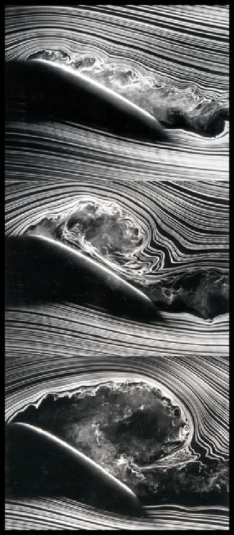
For a fixed-wing aircraft, stall – the point where airflow around the wing separates and lift is lost – is an enemy. It’s the precursor to a stomach-turning freefall for the airplane and its contents. But the story is rather different when the wing is actively pitching through these high angles of attack. In this case, you get what’s known as dynamic stall, illustrated in three consecutive snapshots above.
In the top image, the flow has clearly separated from the upper surface of the wing, but this isn’t a cause for panic. As the middle image shows, there’s a vortex that’s formed in that separated region and it’s moving backward along the wing as the angle of attack continues to increase. That vortex causes a strong low-pressure region on the upper surface of the wing, allowing it to maintain lift.
In the final image, the vortex is leaving the wing, taking its low-pressure zone with it. This is the point where the pitching wing loses its lift, but if the vortex’s departure is immediately followed by a pitch down to lower angles of attack, the aircraft will recover lift and carry on. (Image credit: S. Schreck and M. Robinson, source)
Engineers frequently face the challenge of maintaining control of air flow around an object across a wide range of conditions. After all, wind turbines and airplanes don’t always get to choose the perfect weather. To widen their operating ranges, designers can use active flow control to keep air flowing around an airfoil instead of separating and causing stall. One method of flow control uses plasma actuators on the upper surface of an airfoil. When activated, the plasma actuator ionizes air near the wing surface, producing the purplish glow seen above. That ionized air, or plasma, gets accelerated by the electric field of the device. The acceleration adds momentum to air near the wing surface, which helps it stay attached and flowing smoothly despite the unfavorable pressure conditions near the trailing edge of the wing. Compared to other methods of active flow control, plasma actuation is relatively simple to implement and so is actively being researched for applications in aviation and wind energy. (Image and research credit: I. Brownstein et al., source)
so, how is lift actually generated? i’ve been going through Anderson’s Introduction to Flight (6th Ed.) and while it offers the derivation of various equations very thoroughly, it barely touches on why lift is generated, or how camber contributes to the increase of C(L)
This is a really good question to ask. There are a lot of different explanations for lift out there (and some of the common ones are incorrect). The main thing to know is that a difference in pressure across the wing–low pressure over the top and higher pressure below–creates the net upward force we call lift. It’s when you ask why there’s a pressure difference across the wing that explanations tend to start diverging. To be clear, aerodynamicists don’t disagree about what produces lift – we just tend to argue about which physical explanation (as opposed to just doing the math) makes the most sense. So here are a couple of options:
Newton’s third law states that for every action there is an equal and opposite reaction. If you look at flow over an airfoil, air approaching the airfoil is angled upward, and the air leaving the aifoil is angled downward. In order to change the direction of the air’s flow, the airfoil must have exerted a downward force on the air. By Newton’s third law, this means the air also exerted an upward force–lift–on the airfoil.
The downward force a wing exerts on the air becomes especially obvious when you actually watch the air after a plane passes:
This one can be harder to understand. Circulation is a quantity related to vorticity, and it has to do with how the direction of velocity changes around a closed curve. Circulation creates lift (which I discuss in some more detail here.) How does an airfoil create circulation, though? When an airfoil starts at rest, there is no vorticity and no circulation. As you see in the video above, as soon as the airfoil moves, it generates a starting vortex. In order for the total circulation to remain zero, this means that the airfoil must carry with it a second, oppositely rotating vortex. For an airfoil moving right to left, that carried vortex will spin clockwise, imparting a larger velocity to air flowing over the top of the wing and slowing down the air that moves under the wing. From Bernoulli’s principle, we know that faster moving air has a lower pressure, so this explains why the air pressure is lower over the top of the wing.
Asymmetric Flow and Bernoulli’s Principle
There are two basic types of airfoils – symmetric ones (like the one in the first picture above) and asymmetric, or cambered, airfoils (like the one in the image immediately above this). Symmetric airfoils only generate lift when at an angle of attack. Otherwise, the flow around them is symmetric and there’s no pressure difference and no lift. Cambered airfoils, by virtue of their asymmetry, can generate lift at zero angle of attack. Their variations in curvature cause air flowing around them to experience different forces, which in turn causes differing pressures along the top and the bottom of the airfoil surface. A fluid particle that travels over the upper surface encounters a large radius of curvature, which strongly accelerates the fluid and creates fast, low-pressure flow. Air moving across the bottom surface experiences a lesser curvature, does not accelerate as much, and, therefore, remains slower and at a higher pressure compared to the upper surface.
One of the challenges of experimental fluid dynamics is capturing information about a flow that varies in three spatial dimensions and time. Experimentalists have developed many techniques over the years–some qualitative and some quantitative–all of which can only capture a small portion of the flow. The photos above are a series of laser-induced fluorescence (LIF) images of an airfoil at increasing angles of attack. The green swirls are from an added chemical that fluoresces after being excited with a laser. In this case, the technique is providing flow visualization, showing how flow over the upper surface of the airfoil shifts and separates as the angle of attack increases. The technique can also be used, however, to measure velocity, temperature, and chemical concentration. (Image credit: S. Wang et al.)
In the transonic speed regime the overall speed of an airplane is less than Mach 1 but some parts of the flow around the aircraft break the speed of sound. The photo above shows a schlieren photograph of flow over an airfoil at transonic speeds. The nearly vertical lines are shock waves on the upper and lower surfaces of the airfoil. Although the freestream speed in the tunnel is less than Mach 1 upstream of the airfoil, air accelerates over the curved surface of airfoil and locally exceeds the speed of sound. When that supersonic flow cannot be sustained, a shock wave occurs; flow to the right of the shock wave is once again subsonic. It’s also worth noting the bright white turbulent flow along the upper surface of the airfoil after the shock. This is the boundary layer, which can often separate from the wing in transonic flows, causing a marked increase in drag and decrease in lift. Most commercial airliners operate at transonic Mach numbers and their geometry is specifically designed to mitigate some of the challenges of this speed regime. (Image credit: NASA; via D. Baals and W. Corliss)
Flow around an airfoil with a leading-edge slat is visualized above. At this Reynolds number, alternating periodic vortices are shed in its wake. Understanding how multi-element airfoils and control surfaces affect local flow is important in controlling aircraft aerodynamics. When multiple instabilities interact–like those in the wing’s boundary layer interacting with the wake’s–it can generate disturbances that are problematic in flight. Being able to predict and avoid such behavior is important for safe aircraft. (Photo credit: S. Makiya et al.)
At high angles of attack, the flow around the leading edge of an airfoil can separate from the airfoil, leading to a drastic loss of lift also known as stall. Separation of the flow from the surface occurs because the pressure is increasing past the initial curve of the leading edge and positive pressure gradients reduce fluid velocity; such a pressure gradient is referred to as adverse. One way to prevent this separation from occurring at high angle of attack is to apply suction at the leading edge. The suction creates an artificial negative (or favorable) pressure gradient to counteract the adverse pressure gradient and allows flow to remain attached around the shoulder of the airfoil. Suction is sometimes also used to control the transition of a boundary layer from laminar to turbulent flow.
In recent years unmanned aerial vehicles (UAVs) have grown in popularity for both military and civilian application and are shifting from a remotely controlled platform to autonomous control. Since no pilot flies onboard an UAV, these craft are much smaller than other fixed-wing aircraft, with wingspans that may range from a few meters to only centimeters. At these sizes, most fixed-wing airfoil theory does not apply because no part of the wing is isolated from end effects. This complicates the prediction of lift and drag on the aircraft, particularly during maneuvering and necessitates the development of new predictive methods and control schemes. Shown above are flow visualizations of a small UAV executing a perching maneuver, intended to allow the craft to land as a bird does by scrubbing speed with a high-angle-of-attack, high-drag motion. (Photo credit: Jason Dorfman; via Hizook; requested by mindscrib)


