
This photo shows a prototype of the X-48C blended wing body aircraft being tested in NASA Langley’s 12-Foot Low-Speed Tunnel. Blended wing bodies have many advantages over conventional tube-and-wing designs: the entire surface of the craft can generate lift; the usable cargo/passenger area of the craft is increased; and, structurally, the craft is easier to manufacture. Flight tests of a remote-controlled version of the craft have also taken place.
Search results for: “lift”

Discovery Wingtip Vortices
Wingtip vortices mark the path of Discovery as she makes her final landing. Though not always visible, these vortices are generated by any lifting body planform and can be a major source of induced drag on the craft. Here the vortices are visible because the low pressure in the core of the vortex caused a local temperature drop below the dew point, thus causing condensation. Such vortices persist for significant lengths of time in the wake of aircraft; they are a major source of wake turbulence, which limits how frequently aircraft can take-off or land on a single runway. (Photo by Jen Scheer)

Wright Brothers’ Wind Tunnel
A large part of the Wright Brothers’ ultimate success in creating the first powered heavier-than-air craft came as a result of work done in their homemade wind tunnel, shown above. In the aftermath of the failure of their 1901 Glider, the brothers decided that the lift and drag data they had used from Otto Lilienthal must be inaccurate. They built this wind tunnel and its force balances to measure lift and drag on two hundred different airfoils themselves and were rewarded with far more successful flights with their 1902 Glider, which led directly to the Wright Flyer in the following year. #

Reader Question: Rotor Ships
lazenby asks:
Can you explain how the magnus effect makes rotor ships move?
When a spinning body is placed in a flow, the body experiences a force perpendicular to the direction of the flow. This is called the Magnus effect and is, for example, why baseballs, soccer balls, and tennis balls veer from the path we expect them to take. To understand why a spinning body experiences this force, take a look at the streamlines around a rotating cylinder.
In this picture, the flow goes from left to right and the cylinder is spinning in the clockwise direction. The red dots represent the stagnation points of the flow. Air over the top of the cylinder gets accelerated by the spinning, shown here by the narrowing of space between streamlines. On the underside of the cylinder, the surface is moving in the opposite direction of the air, which decelerates the flow. We know from Bernoulli that this means there is low pressure on the top of the cylinder and high pressure on the bottom. As a result, the cylinder experiences a upward force – lift! You can explore the effect of rotation on the streamlines yourself using this neat demo from Wolfram.
Rotor ships, invented in the 1920s, used this effect for ship’s propulsion. They used a regular motor to begin moving, and, once they had some wind, used motors to spin giant cylinders on the deck. As the rotors spun, the ships were pushed in a direction perpendicular to the wind. They could apparently tack 20-30 degrees into the wind while conventional ships could only manage 45 degrees. Unfortunately, so much energy was required to spin the rotors that the design was pretty inefficient and never caught on.
Reader Question: Hot Air Balloon Physics
lazenby asks:
and boyancy in air? is the lifting capacity of a hot air balloon equal to the modulo of the weight of the air in the balloon with the weight of the same volume of air outside the balloon?
for that matter, does the lift of a big helium weather balloon decrease as air pressure, and so weight of the air outside the balloon, drops? and is this exactly counterbalanced by the lessening density of the helium in the balloon?
all of these things keep me awake.
Hopefully you won’t be sleepless much longer. Buoyancy in air follows the same principles as buoyancy in water. Determining the lifting capacity of a balloon is a matter of determining how heavy the balloon can be before the buoyant force is equal to the weight. See the free body diagram and little derivation below to see what the maximum payload mass is for a helium balloon. You can click on the picture to enlarge it.

The second part of your question raises some interesting points. As a balloon’s altitude increases, the atmosphere around it gets colder and less dense, all of which should reduce the buoyant force. At the same time, the balloon itself expands to equalize the pressure inside and outside of the balloon, which should increase the buoyant force. (At some point the pressure drops sufficiently that the tensile strength of the balloon material is unable to cope with that expansion and the balloon bursts, but we’ll ignore that here.) For this problem, we’d want to know what payload the balloon can carry without losing lift, and, with a couple assumptions, that’s pretty easy to figure out. I’ve done that derivation below.

The real key to the calculation is assuming that the helium in the balloon maintains the same temperature as the air outside. Since balloons rise slowly, this seemed a more reasonable assumption than imagining that the balloon remains warm compared to its surroundings. That calculation is doable as well but requires more than a couple lines, unfortunately! Thanks for your questions!
Frost on Superhydrophobic Surfaces
Frost formation and ice adhesion on superhydrophobic surfaces
For anyone with further interest in the ice formation on superhydrophobic surfaces story we posted recently, the published paper is currently offered by AIP for free. #
Frosting on Superhydrophobic Surfaces
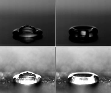
Icing on airplane wings can be disastrous for lift and control, and thus how ice initially forms on a wing is an active area of research. New work shows that superhydrophobic (water-fearing) surfaces may actually promote ice buildup. Superhydrophobic surfaces are prone to frosting–collecting ice that forms directly from a vaporous state–and that fine layer of frost is conducive to further ice buildup from a liquid state. The photo above shows a water droplet striking a dry superhydrophobic surface (top) and a frosted superhydrophobic surface (bottom). (via Gizmodo) #
Tubercles and Turbines
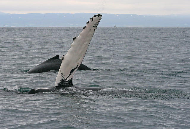
The flippers of humpback whales include bumps–called tubercles–on their leading edges. The tubercles create vortices that prevent the boundary layer from separating, which causes stall and a loss of lift. New research shows that adding similar bumps to the leading edge of tidal turbine blades results in greater energy production at low flow speeds compared to conventional designs. See Scientific American for more. #

Pterosaur Aerodynamics
The pterosaur was an enormous prehistoric reptile that flew with wings of living membrane stretched over a single long bone, unlike any of today’s flying creatures. New research using carbon fiber wing analogues and wind tunnel testing suggests that the pterosaur would have been a slow, soaring flyer well adapted to using thermals for lift. Once on a thermal, the pterosaur could coast, perhaps for hours at a time, with little to no flapping necessary. See the research paper or the Scientific American article for more. #

Flying Snakes Draft off Themselves
Some snakes in Southeast and South Asia are known to glide some 100 m between trees. Researchers filmed snakes, constructed computational models of their flights, and tested plastic models in a water tunnel. They found that the snakes angled their bodies such that they generate lift to counteract their fall and that the S-configuration they assume increases lift much the way flying in a V-formation does for geese. The wake from the forward portion of the snake interacts with the flow around the back of the snake and reduces downwash, which increases lift. In effect, the back of the snake is drafting off the front. #