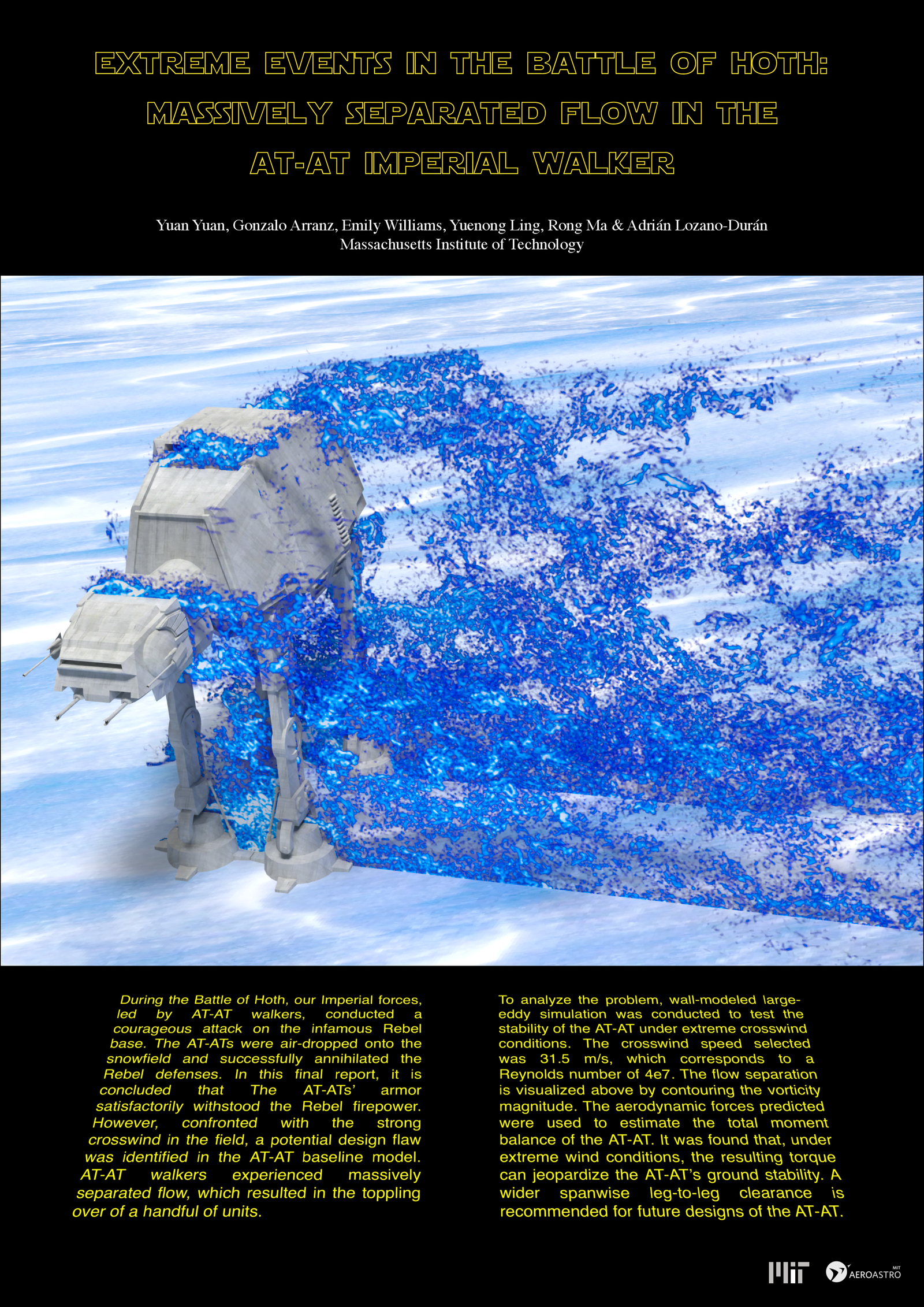
Having previously examined the re-entry characteristics of an X-Wing, a group of engineers are back to look at Imperial vehicle physics. In this poster, they look at what happens to the AT-AT walker when strong crosswinds, like those seen in the Battle of Hoth, blow across the vehicle’s path. Given its boxy body and gangly legs, it will come as no surprise that the AT-AT is not at all streamlined and instead causes lots of separated flow. Those flow separations come with strong side forces that can tip the walkers.
Be sure to take a closer look at the text on the poster. It’s written from the perspective of Imperial engineers, complete with recommendations for the next generation of AT-AT. (I don’t think those got built, at least not by the Empire!) May the 4th be with you! (Image credit: Y. Yuan et al.)
For a long time, people thought baseball aerodynamics were simply a competition between gravity and the Magnus effect caused when a ball is spinning. But the seams of a baseball are so prominent that they, too, have a role to play. Here’s a baseline image of flow around a non-spinning baseball:
An non-spinning baseball with a straight, unaltered wake.
As in our previous post on golf, the colors indicate the direction of vorticity but don’t matter much to us here. What’s important is that the wake behind the ball is straight, indicating that there is no additional force beyond gravity and drag acting on the ball. Contrast this to the spinning baseball below:
Flow around a baseball spinning clockwise.
This ball is spinning in a clockwise motion, which causes flow to separate from the ball earlier on the advancing (bottom) side and later on the retreating (top) side. As a result, the wake is tilted downward. This indicates an upward force on the ball, caused by the Magnus effect.
But what if the seams fall in a place where they affect the flow? Here’s another baseball that’s not spinning:
Flow around a non-spinning baseball with a seam-shifted wake caused by early separation on the top surface of the baseball.
Notice that seam sitting just past the widest point on the top of the baseball. Flow around that wide point (called the shoulder) is very sensitive to disturbances essentially because the boundary layer is just barely hanging on to the ball. The blue arrow marks where the boundary layer separates from the ball on the top, which takes place earlier than the flow separation on the bottom, marked by the red arrow. As a result, the wake of the ball is tilted upward, indicating a downward force on the ball. The researchers who first proved this effect call it a seam-shifted wake, and it turns out to be a very common effect in baseball. They’ve got a great blog dedicated to baseball aerodynamics where you can learn tons more if you’re interested. (Image credit: top – Pixabay, others – B. Smith; research credit: B. Smith; see also Baseball Aerodynamics)
Today wraps up our Olympic coverage, but if you missed our earlier posts, you can find them all here.
Golf returned to the Olympics in 2016 in Rio and is back for the Tokyo edition. Golf balls — with their turbulence-promoting dimples — are a perennial favorite for aerodynamics explanations because, counterintuitively, a dimpled golf ball flies farther than a smooth one. But today we’re going to focus on a different aspect of golf aerodynamics, namely, what happens when a golf ball is spinning. Here’s an animation showing the difference between flow around a non-spinning golf ball and flow around a golf ball spinning at 3180 rpm. Both balls are moving to the left at 30 m/s.
Animation toggling between a non-spinning and spinning golf ball moving at 30 m/s.
The colors in this image indicate the direction of vorticity (which is unimportant for us at the moment). What matters are the blue and red arrows, which mark where flow is leaving the surface of the golf ball, in other words, where the wake begins. For the non-spinning golf ball, flow leaves the ball at the same streamwise position on both sides of the ball. This gives a symmetric wake that is neither tilted upward nor downward.
On the spinning ball, though, the blue arrow on top of the ball moves backward, indicating that separation occurs later. On the lower surface, the red arrow moves forward, so separation happens earlier. These shifts cause the golf ball’s wake to tilt downward, which — by Newton’s Third Law — tells us that the ball is experiencing an upward force. This is known as the Magnus effect, and it plays a big role in soccer, volleyball, tennis, and any other sports with spinning balls.
Like footballs and baseballs, the trajectory of a volleyball is strongly influenced by aerodynamics. When spinning, the ball experiences a difference in pressure on either side, which causes it to swerve, per the Magnus effect. But volleyball also has the float serve, which like the knuckleball in baseball, uses no spin.
In this case, how the ball behaves depends strongly on the way the ball is made. Some volleyballs use smooth panels, while others have surfaces modified with dimples or honeycomb patterns, and researchers found that these subtle changes make a big difference in aerodynamics. A float serve’s trajectory is unpredictable because the ball will swerve whenever air near the surface of the ball on one side goes turbulent or separates. And without spin to influence that transition, everything comes down to the ball’s speed and its surface.
Researchers found that volleyballs with patterned surfaces transition to turbulence at lower speeds, which makes their behavior more predictable overall. But players who want to maximize the unpredictability of their float serve might prefer smooth-paneled balls, which don’t make the transition until higher speeds. (Image credit: game – Pixabay, volleyballs – U. Tsukuba; research credit: S. Hong et al., T. Asai et al.; via Ars Technica)
Stick around all this week and next for more Olympic-themed fluid physics!
Vortex ring impacts are eternally fascinating. Here, researchers explore what happens when a vortex ring encounters a V-shaped wall. Because the outer portions of the vortex ring hit the wall sooner than the inner ones, distortions begin there first.
The vortex’s approach creates a pressure gradient that causes flow near the wall to separate, generating that first little hook in each arm of the vortex. Next, secondary vortices develop on either side and quickly get pulled into the original vortex. The whole process repeats a second time to generate tertiary vortices that continue the inward spiral. The impact appears even more complicated when viewed from the side of the valley (Image 2). Check out Image 3 for a point-by-point breakdown of the impact process. (Image and research credit: T. New et al.)
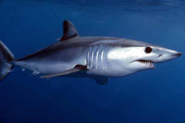
The speedy shortfin mako shark has a secret weapon to fight drag: bristling denticles that line its fins and tail. Denticles are tiny, anvil-shaped enamel scales on the mako’s skin. In the photo above, each one is about 100 microns across. Under normal conditions, with flow moving over the shark from nose to tail, the denticles lie flat, providing no interference.
But when sudden changes in flow near the shark’s skin cause water to begin moving in the opposite direction, the denticles flare up. Their rise interferes with the reversed flow, trapping it in small eddies beneath each denticle. Since that flow reversal is a precursor to the flow separating from the shark’s body, the bristling effectively cuts off flow separation before it can begin. The result is much less separation and much lower drag. Once the flow stops trying to move upstream, the denticles settle back into their original place. (Image credit: mako shark – jidanchaomian, denticles – J. Oeffner and G. Lauder, illustration – A. Lang, bristling – A. Lang et al.; research credit: A. Lang and A. Lang et al.; submitted by Kam-Yung Soh)
Fixed-wing flight typically favors the efficiency of long skinny wings, which is why so many aircraft have them. But for smaller flyers, like micro air vehicles (MAVs), short and stubby wings are necessary to stand up the disruption of sudden wind gusts. But a new MAV design eschews that conventional wisdom in favor of a biological tactic: intentionally disrupting the flow.
Usually designers aim to have a smooth, rounded leading edge to wings in order to guide air around the airfoil. But here researchers instead chose a sharp, thick leading edge that immediately disrupts the flow, causing a turbulent separation region over the front section of the wing. A rounded flap added over the trailing edge of the wing guides flow back into contact, giving the wing its lift generation.
Odd as that design choice seems at first blush, it actually makes the aircraft extremely resilient, especially to the turbulence that so often thwarts small flyers. When your flow is already disrupted, a little extra turbulence doesn’t make a difference.
The thicker wing also allows them to use a longer wingspan — thereby gaining that skinny wing efficiency — and move most of the components that would normally be in a fuselage into the wings themselves. By essentially turning most of the MAV into a wing, the designers avoid the loss of lift associated with the fuselage section of the wings.
Even in an era of supercomputers, there is a place for quick and dirty methods of flow visualization. Here we see a model of a swept wing like those seen on many commercial airliners. It was painted with a layer of fluorescent oil, then placed in a wind tunnel and subjected to flow. As air blows across the model, it moves the oil, leaving behind streaks that show how air near the surface moves.
We can see, for example, that near the fuselage, the air flows mostly front to back across the wing. That’s what we expect, especially for a wing generating lift. But further out on the wing, the flow moves mostly along the wing, not across it. There’s also a distinctive line running just a short ways behind the leading edge on this outer section of wing. It looks as though air flowing over the wing separated at this point, leaving disordered and unhelpful flow behind. It’s likely that the model was tested at an angle of attack where the outer section of the wing was beginning to stall. (Image credit: ARA)
Over the years, there have been many odd airplane designs, but one you probably haven’t seen much is the forward-swept wing. While most early aircraft featured straight wings, rear-swept wings are fairly common today, especially among commercial airliners. A rear-swept wing has its forward-most point at the root of the ring, where it attaches to the fuselage. The sweep breaks up the incoming flow into a chordwise component that flows from the leading edge to the trailing edge of the wing and a spanwise component that flows along the wing. Compared to straight wings, a swept wing provides better stability and control when flying at transonic speeds where shock waves can form on the wing (even though the plane itself is not supersonic).
The trouble with rear-swept wings is that when they stall, they do so from the wingtips inward. Since the ailerons that control the plane’s orientation are out near the wingtips, that’s a problem. Forward-swept wings were supposed to solve this issue because they would stall from the root outward. But they came with a whole new set of problems, which included the need for robust onboard computers controlling them constantly to keep them in stable flight. In the end, the disadvantages outweighed any gains and so, for the most part, the forward-swept wing design has seen little flight time. (Image and video credit: Real Engineering)
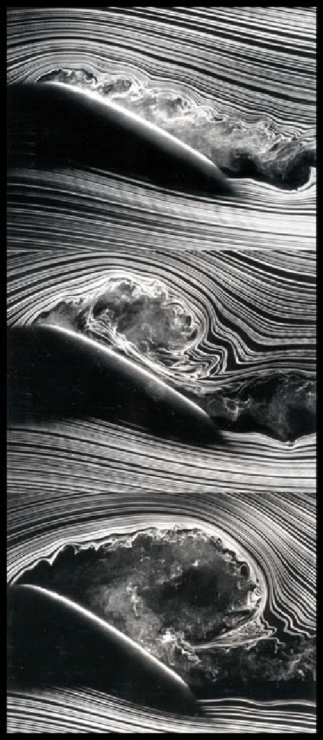
For a fixed-wing aircraft, stall – the point where airflow around the wing separates and lift is lost – is an enemy. It’s the precursor to a stomach-turning freefall for the airplane and its contents. But the story is rather different when the wing is actively pitching through these high angles of attack. In this case, you get what’s known as dynamic stall, illustrated in three consecutive snapshots above.
In the top image, the flow has clearly separated from the upper surface of the wing, but this isn’t a cause for panic. As the middle image shows, there’s a vortex that’s formed in that separated region and it’s moving backward along the wing as the angle of attack continues to increase. That vortex causes a strong low-pressure region on the upper surface of the wing, allowing it to maintain lift.
In the final image, the vortex is leaving the wing, taking its low-pressure zone with it. This is the point where the pitching wing loses its lift, but if the vortex’s departure is immediately followed by a pitch down to lower angles of attack, the aircraft will recover lift and carry on. (Image credit: S. Schreck and M. Robinson, source)