Search results for: “airfoil”

  • Featured Video Play Icon

    Sochi 2014: Speed Skiing

    As FYFD wraps up coverage of #Sochi2014, let’s take a look at a winter sport not currently contested at the Olympics. This year’s Winter Games featured 12 new events. Speed skiing was not among them, though it was a demonstration sport in the 1992 Olympics. Like many of the sports in Sochi, speed skiing is gravity-driven, and friction and drag serve only to slow competitors. Speed skiing is about getting from the top of the course to the bottom, in a straight line, as fast as possible. Athletes reach velocities as high as 250 kph (155 mph), and aerodynamics are of the utmost concern. The skiers’ rubberized speed suits include airfoil-shaped fairings behind their calves that mold the airflow, and athletes wear giant aerodynamic helmets to smooth flow over their heads and shoulders. They spend their entire descent in an aerodynamic tuck, arms extended ahead of them like a cyclist in a time trial. It looks a pretty crazy ride. Would you like to see it added to the Olympics? (Video credit: R. Sill/University of Cambridge)

    FYFD is celebrating #Sochi2014 with a look at fluid dynamics in winter sports. Check out the previous poss on why ice is slippery, the aerodynamics of speedskating, and how lugers slide fast.

  • Featured Video Play Icon

    Fluid Juggling

    It’s that time of the year – the 2013 APS Division of Fluid Dynamics meeting is not far off, and entries to this year’s Gallery of Fluid Motion are starting to appear. This week we’ll be taking a look at some of the early video submissions, beginning with one that you can recreate at home. This video demonstrates a neat interaction between a slightly-inclined liquid jet and a lightweight ball. The jet can stably support–or, as the authors suggest, juggle–the ball under many circumstances, as seen in the video. Initially, the jet impacts near the bottom of the ball and then spreads into a thin film over the surface. This decrease in thickness between the jet and the film is accompanied by an increase in speed due to conservation of mass. That velocity increase in the film corresponds to a pressure decrease because of Bernoulli’s principle. This means that there is a region of higher pressure where the jet impacts the ball and lower pressure where the film flows around the ball. Just as with airflow over an airfoil, this generates a lift force that holds the ball aloft. (Video credit: E. Soto and R. Zenit)

  • Featured Video Play Icon

    Wind Tunnel Testing

    Wind tunnel testing is an important step in designing new aircraft. This video shows footage of visualization tests of the 21-ft wingspan Boeing X-48C model in NASA Langley’s Full-Scale Tunnel. The X-48C is a blended wing body design capable of higher lift-to-drag ratios than conventional aircraft, which should lead to a higher range and greater fuel economy. The video shows some smoke visualization that illustrates airflow around the airfoil-shaped craft. The long probe sticking forward from the starboard wing is used to measure air pressure, angle of attack, and sideslip angle of the model. Notice how smoke from the wand is pulled from below the leading edge of the wing up and over the top of the wing. This is because there is lower pressure over the top of the wing than the bottom, and, like an electrical charge seeking the path of least resistance, fluids flow preferentially toward lower pressures. (Video credit: NASA Langley)

  • Fluids Round-up – 24 August 2013

    Fluids Round-up – 24 August 2013

    Fluids round-up time! Here are your latest fluids links to check out:

    (Photo credit: G. Pretor-Pinney)

  • Featured Video Play Icon

    Flapping Foil Wake

    This gorgeous visualization shows the flow behind a flapping foil. Flow in the water tunnel is from right to left, with dye introduced to show streamlines. A flapping foil is a good base model for most flapping flight as well as finned swimming – anything that oscillates to create thrust. As the foil flaps, vorticity is generated and shed along the trailing edge, creating a regularly patterned wake of trailing vortices. (Video credit: R. Godoy-Diana)

  • The Silence of Owls

    The Silence of Owls

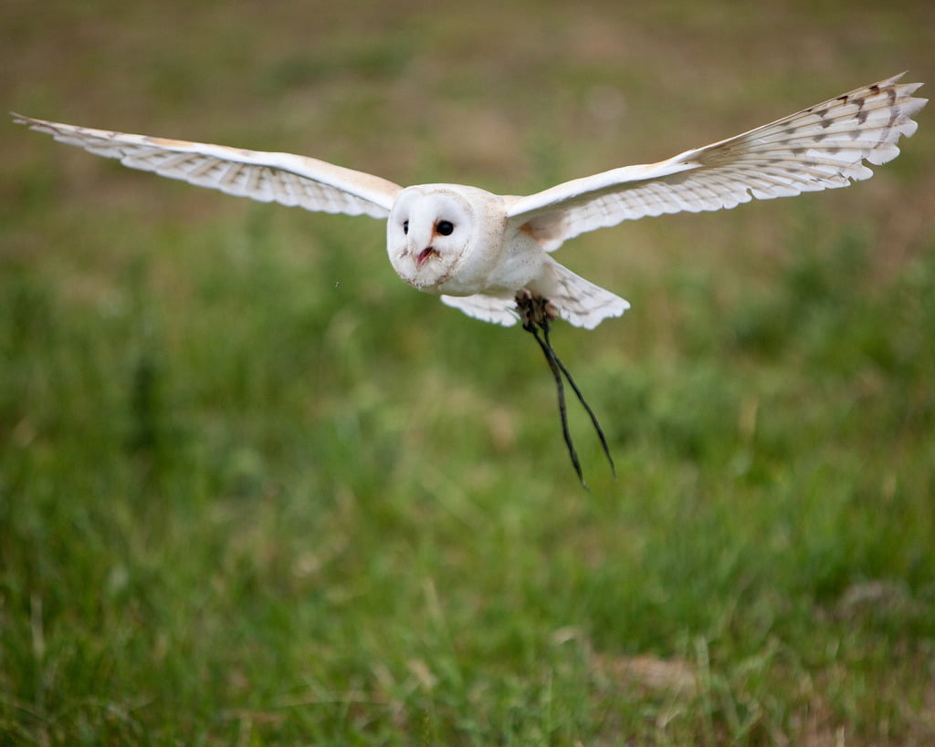
    Owls are nearly silent hunters, able to swoop down on their prey without the rush of air over their wings giving away their approach, thanks to several key features of their feathers. The trailing edge of their feathers–or any lifting body, like an airplane wing–are a particular source of acoustic noise due to the interaction of turbulence near the surface with the edge. Since owls are especially good at eliminating self-produced noise in a frequency range that overlaps human hearing, investigators want to learn what works for owls and apply to it aircraft. A recent theoretical analysis uses a simplified model of the feather as a porous, elastic plate. The researchers found that the combination of porosity with the elasticity of the trailing edge significantly reduced noise relative to a rigid edge. (Photo credit: N. Jewell; research credit: J. Jaworski and N. Peake)

  • Stalling

    [original media no longer available]

    At high angles of attack, the flow around the leading edge of an airfoil can separate from the airfoil, leading to a drastic loss of lift also known as stall. Separation of the flow from the surface occurs because the pressure is increasing past the initial curve of the leading edge and positive pressure gradients reduce fluid velocity; such a pressure gradient is referred to as adverse. One way to prevent this separation from occurring at high angle of attack is to apply suction at the leading edge. The suction creates an artificial negative (or favorable) pressure gradient to counteract the adverse pressure gradient and allows flow to remain attached around the shoulder of the airfoil. Suction is sometimes also used to control the transition of a boundary layer from laminar to turbulent flow.

  • Unmanned Aerial Vehicles

    Unmanned Aerial Vehicles

    In recent years unmanned aerial vehicles (UAVs) have grown in popularity for both military and civilian application and are shifting from a remotely controlled platform to autonomous control. Since no pilot flies onboard an UAV, these craft are much smaller than other fixed-wing aircraft, with wingspans that may range from a few meters to only centimeters. At these sizes, most fixed-wing airfoil theory does not apply because no part of the wing is isolated from end effects. This complicates the prediction of lift and drag on the aircraft, particularly during maneuvering and necessitates the development of new predictive methods and control schemes. Shown above are flow visualizations of a small UAV executing a perching maneuver, intended to allow the craft to land as a bird does by scrubbing speed with a high-angle-of-attack, high-drag motion. (Photo credit: Jason Dorfman; via Hizook; requested by mindscrib)

  • Featured Video Play Icon

    Magnus Force

    Physics students are often taught to ignore the effects of air on a projectile, but such effects are not always negligible. This video features several great examples of the Magnus effect, which occurs when a spinning object moves through a fluid. The Magnus force acts perpendicular to the spin axis and is generated by pressure imbalances in the fluid near the object’s surface. On one side of the spinning object, fluid is dragged with the spin, staying attached to the object for longer than if it weren’t spinning.  On the other side, however, the fluid is quickly stopped by the spin acting in the direction opposite to the fluid motion. The pressure will be higher on the side where the fluid stagnates and lower on the side where the flow stays attached, thereby generating a force acting from high-to-low, just like with lift on an airfoil. Sports players use this effect all the time: pitchers throw curveballs, volleyball and tennis players use topspin to drive a ball downward past the net, and golfers use backspin to keep a golf ball flying farther. (Video credit: Veritasium)

  • London 2012: Cycling Physics

    London 2012: Cycling Physics

    In no discipline of cycling is more emphasis placed on fluid dynamics than in the individual time trial.  This event, a solo race against the clock, leaves riders no place to hide from the aerodynamic drag that makes up 70% or more of the resistance riders overcome when pedaling. Time trial bikes are designed for low drag and light weight over maneuverability, using airfoil-like shapes in the fork and frame to direct airflow around the bike and rider without separation, which creates an area of low pressure in the wake that increases drag.  Riders maintain a position stretched out over the front wheel of the bike, with their arms close together.  This position reduces the frontal area exposed to the flow, which is proportional to the drag a rider experiences.

    Special helmets, some with strangely streamlined curves, are used to direct airflow over the rider’s head and straight along his or her back. Both helmets and skinsuits are starting to feature areas of dimpling or raised texturing. These function in much the same way as a golf ball; the texture causes the boundary layer, the thin layer of air near a surface, to become turbulent.  A turbulent boundary layer is less susceptible to separating from the surface, ultimately leading to lower drag than would be observed if the boundary layer remained laminar. Wheels, skinsuits, gloves, shoe covers, and even the location of the brakes on the bike are all tweaked to reduce drag.  In an event that can be decided by hundredths of a second between riders, every gram of drag counts. (Photo credits: Stefano Rellandini, POC Sports, Reuters, Paul Starkey, Louis Garneau)

    FYFD is celebrating the Olympics by featuring the fluid dynamics of sports. Check out our previous posts on how the Olympic torch works, what makes a pool fast, the aerodynamics of archery, and the science of badminton.