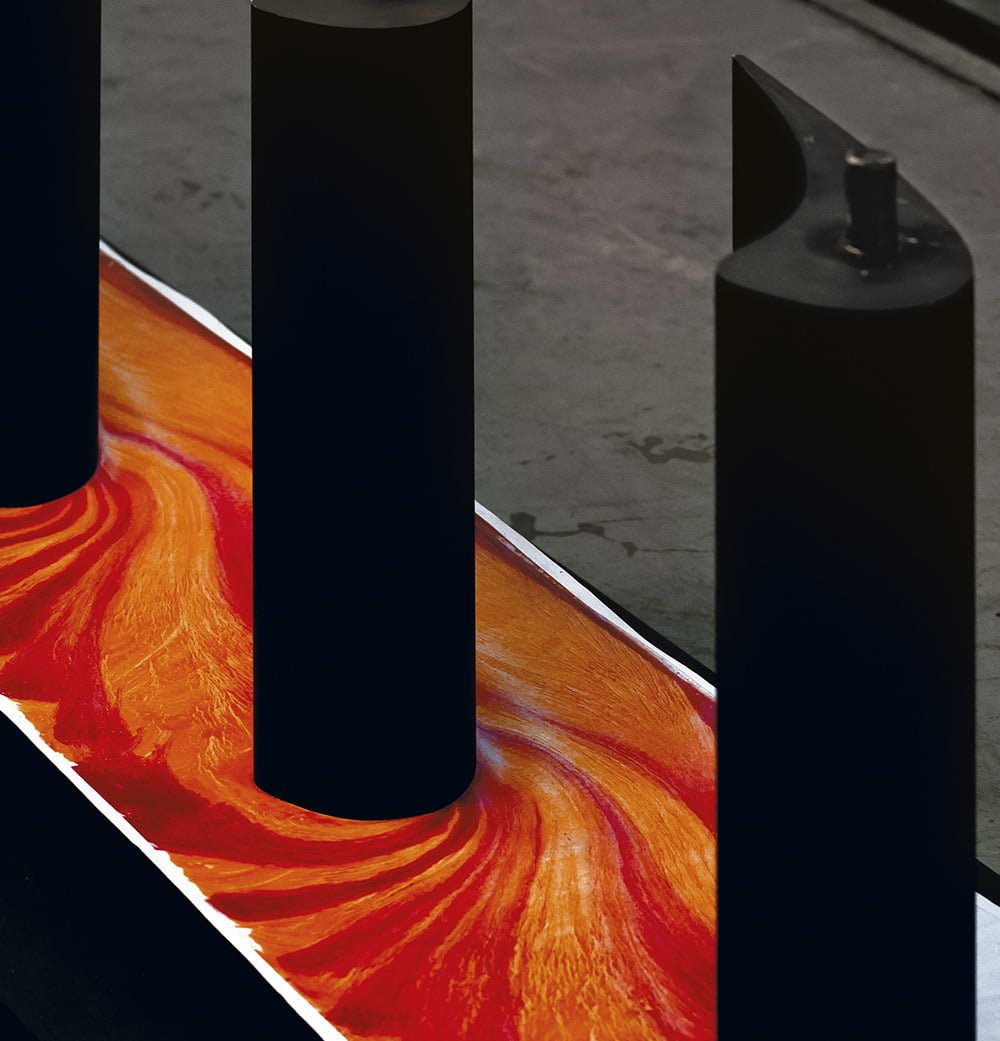
Fluid flows are complex, complicated, and ever-changing. Researchers use many techniques to visualize parts of a flow, which can help make what’s happening clearer. One technique, shown above, uses oil and dye to visualize flow at the surface. The vertical, black, airfoil-shaped pieces are stators, stationary parts within a turbine that help direct flow. After painting the stator mount surface with a uniform layer of oil, the model can be placed in a wind tunnel (or turbine) and exposed to flow. Air moving around the stators drags some of the oil with it, creating the darker and lighter streaks seen here. Notice how the lines of oil turn sharply around the front of the stator and bunch up near its widest point. Those crowded flow lines tell researchers that the air moves quickly around this corner. (Image credit: D. Klaubert et al., source)
Search results for: “airfoil”

Reader Question: Rudders
Reader le-mec writes:
My question involves “fenestrated rudders”, a Chinese invention that
involved cutting diamond-shaped holes in the rudders of ancient Chinese
sailing ships (known as Junks). According to several articles (on the
internet, ha ha), it reduces the amount of effort required to steer the
ship at higher speeds with “no loss of function”. All I can find is
anecdotal evidence and I’d like to know if these claims hold water or if
they’re just steering us in the wrong direction.First off:

Now, I’m no expert on ships or sailing, but let’s talk rudders. Ships use rudders for steering. The rudder is completely submerged and turning it deflects water and creates a side force that helps steer a boat. In essence, it’s an underwater wing that generates lift in the side-to-side direction. Modern rudders even have the same shape as airfoils. That’s clearly not the case with the rudders of Chinese junks, but flat plates are a lot easier to make.
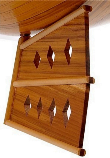
There’s another key feature of the junk’s rudder, and that’s the way it’s mounted. The junk’s rudder attaches to the ship such that it rotates about its leading edge. This makes it an unbalanced rudder. More modern rudders are typically mounted so that they rotate around an axis that’s partway back on the rudder. This is called a balanced rudder; I’ve illustrated both below.

The advantage of the balanced rudder is that it’s easier to turn. You can see this for yourself without adding water into the equation. Imagine holding a big rectangular sheet. If you hold it by one edge and try to rotate it, you can do it, but it’s kind of difficult. If you instead hold it about a third of the way across, you’ll find rotating it easier. Once you have a fluid moving past, it will only magnify how hard it is to turn the rudder.
So the Chinese junks had rudders that were harder to handle (by later ship-building standards) to begin with. By putting holes in the rudder, they equalized the pressure on either face of the rudder. That does make it easier to steer, since the helmsman is no longer fighting pressure differences across the rudder, but it would also reduce steering efficiency. It’s likely, however, given the slow speed of the junks, large rudder area, and their low hydrodynamic efficiency to begin with, that any drop in efficiency was negligible compared to the reduction in force necessary to steer.
Since modern designs rely on foil shapes to generate pressure differences (and therefore side force) across the rudder, adding holes to them would be a bad idea. But back in the Song dynasty, the fenestrated rudder was major advance in nautical engineering!
(Image credits: Chinese junk ship model – Premier Ship Models; Joffrey applauding – HBO; Rudder diagram – N. Sharp)

Plasma Flow Control

Engineers frequently face the challenge of maintaining control of air flow around an object across a wide range of conditions. After all, wind turbines and airplanes don’t always get to choose the perfect weather. To widen their operating ranges, designers can use active flow control to keep air flowing around an airfoil instead of separating and causing stall. One method of flow control uses plasma actuators on the upper surface of an airfoil. When activated, the plasma actuator ionizes air near the wing surface, producing the purplish glow seen above. That ionized air, or plasma, gets accelerated by the electric field of the device. The acceleration adds momentum to air near the wing surface, which helps it stay attached and flowing smoothly despite the unfavorable pressure conditions near the trailing edge of the wing. Compared to other methods of active flow control, plasma actuation is relatively simple to implement and so is actively being researched for applications in aviation and wind energy. (Image and research credit: I. Brownstein et al., source)
The Challenges of Micro Air Vehicles
Interest in micro-aerial vehicles (MAVs) has proliferated in the last decade. But making these aircraft fly is more complicated than simply shrinking airplane designs. At smaller sizes and lower speeds, an airplane’s Reynolds number is smaller, too, and it behaves aerodynamically differently. The photo above shows the upper surface of a low Reynolds number airfoil that’s been treated with oil for flow visualization. The flow in the photo is from left to right. On the left side, the air has flowed in a smooth and laminar fashion over the first 35% of the wing, as seen from the long streaks of oil. In the middle, though, the oil is speckled, which indicates that air hasn’t been flowing over it–the flow has separated from the surface, leaving a bubble of slowly recirculating air next to the airfoil. Further to the right, about 65% of the way down the wing, the flow has reattached to the airfoil, driving the oil to either side and creating the dark line seen in the image. Such flow separation and reattachment is common for airfoils at these scales, and the loss of lift (and of control) this sudden change can cause is a major challenge for MAV designers. (Image credit: M. Selig et al.)

Magnus Effect
Putting a little bit of spin on an object can have a big aerodynamic effect, thanks to the Magnus effect. As demonstrated in the video above, backspin on a basketball dropped from a big height will send it flying out and away. The reason spinning objects generate these counterintuitive motions is because the air flow over them creates differential pressures. On the side of the ball spinning with the flow, air is accelerated, dropping the local pressure; whereas on the opposite side, the ball spinning against the direction of flow makes the flow separate and no longer flow smoothly along that side. This causes a high pressure on that side. Like the difference in pressure on either side of an airfoil, the pressure difference across the ball creates a force that pushes the ball toward the low pressure side. Check out some of the other places Magnus effect shows up! (Video credit: Veritasium; submitted by Andrew C.)
——————
Help us do some science! I’ve teamed up with researcher Paige Brown Jarreau to create a survey of FYFD readers. By participating, you’ll be helping me improve FYFD and contributing to novel academic research on the readers of science blogs. It should only take 10-15 minutes to complete. You can find the survey here.

Reader Question: Lift
everyonelikespotatissallad asks:
so, how is lift actually generated? i’ve been going through Anderson’s Introduction to Flight (6th Ed.) and while it offers the derivation of various equations very thoroughly, it barely touches on why lift is generated, or how camber contributes to the increase of C(L)
This is a really good question to ask. There are a lot of different explanations for lift out there (and some of the common ones are incorrect). The main thing to know is that a difference in pressure across the wing–low pressure over the top and higher pressure below–creates the net upward force we call lift. It’s when you ask why there’s a pressure difference across the wing that explanations tend to start diverging. To be clear, aerodynamicists don’t disagree about what produces lift – we just tend to argue about which physical explanation (as opposed to just doing the math) makes the most sense. So here are a couple of options:
Newton’s third law states that for every action there is an equal and opposite reaction. If you look at flow over an airfoil, air approaching the airfoil is angled upward, and the air leaving the aifoil is angled downward. In order to change the direction of the air’s flow, the airfoil must have exerted a downward force on the air. By Newton’s third law, this means the air also exerted an upward force–lift–on the airfoil.
The downward force a wing exerts on the air becomes especially obvious when you actually watch the air after a plane passes:
This one can be harder to understand. Circulation is a quantity related to vorticity, and it has to do with how the direction of velocity changes around a closed curve. Circulation creates lift (which I discuss in some more detail here.) How does an airfoil create circulation, though? When an airfoil starts at rest, there is no vorticity and no circulation. As you see in the video above, as soon as the airfoil moves, it generates a starting vortex. In order for the total circulation to remain zero, this means that the airfoil must carry with it a second, oppositely rotating vortex. For an airfoil moving right to left, that carried vortex will spin clockwise, imparting a larger velocity to air flowing over the top of the wing and slowing down the air that moves under the wing. From Bernoulli’s principle, we know that faster moving air has a lower pressure, so this explains why the air pressure is lower over the top of the wing.
Asymmetric Flow and Bernoulli’s Principle

There are two basic types of airfoils – symmetric ones (like the one in the first picture above) and asymmetric, or cambered, airfoils (like the one in the image immediately above this). Symmetric airfoils only generate lift when at an angle of attack. Otherwise, the flow around them is symmetric and there’s no pressure difference and no lift. Cambered airfoils, by virtue of their asymmetry, can generate lift at zero angle of attack. Their variations in curvature cause air flowing around them to experience different forces, which in turn causes differing pressures along the top and the bottom of the airfoil surface. A fluid particle that travels over the upper surface encounters a large radius of curvature, which strongly accelerates the fluid and creates fast, low-pressure flow. Air moving across the bottom surface experiences a lesser curvature, does not accelerate as much, and, therefore, remains slower and at a higher pressure compared to the upper surface.
(Image credit: M. Belisle/Wikimedia; National Geographic/BBC2; O. Cleynen/Wikimedia; video credit: J. Capecelatro et al.)

Laser-Induced Fluorescence
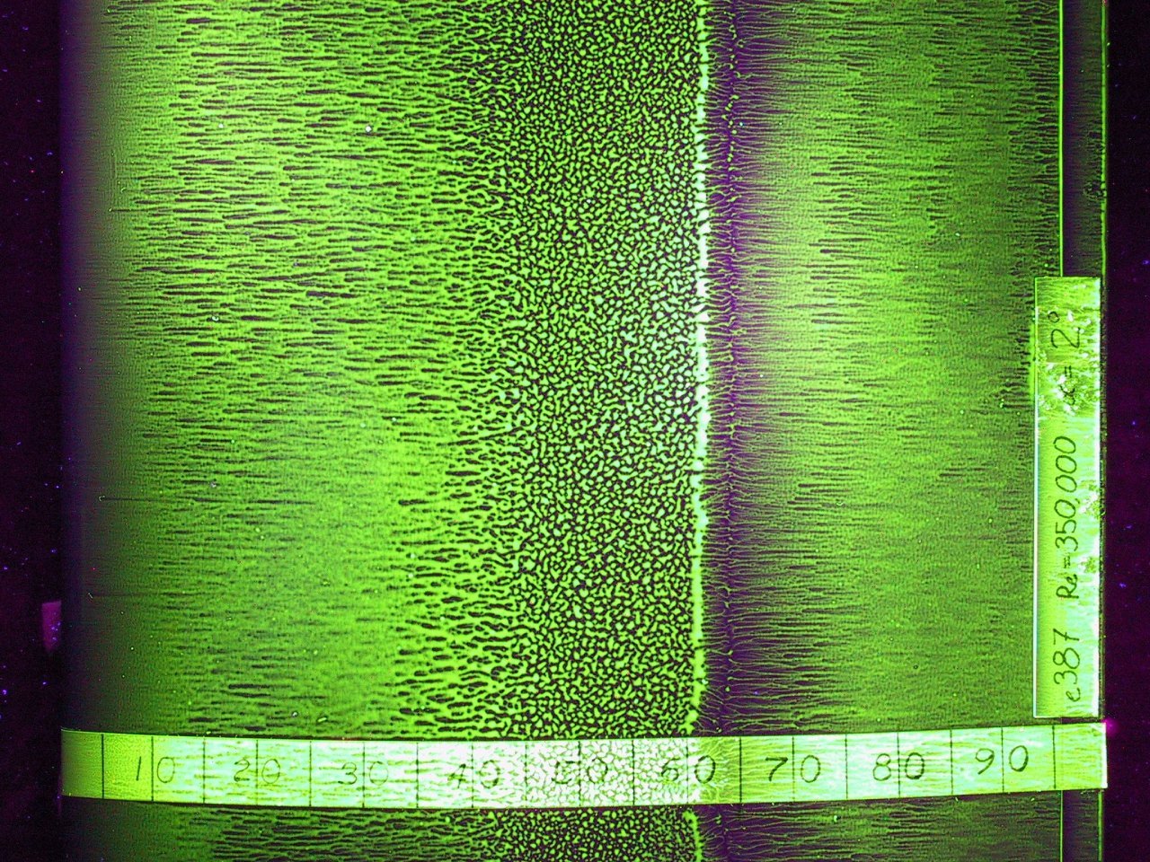
One of the challenges of experimental fluid dynamics is capturing information about a flow that varies in three spatial dimensions and time. Experimentalists have developed many techniques over the years–some qualitative and some quantitative–all of which can only capture a small portion of the flow. The photos above are a series of laser-induced fluorescence (LIF) images of an airfoil at increasing angles of attack. The green swirls are from an added chemical that fluoresces after being excited with a laser. In this case, the technique is providing flow visualization, showing how flow over the upper surface of the airfoil shifts and separates as the angle of attack increases. The technique can also be used, however, to measure velocity, temperature, and chemical concentration. (Image credit: S. Wang et al.)
Hydrofoil Cavitation
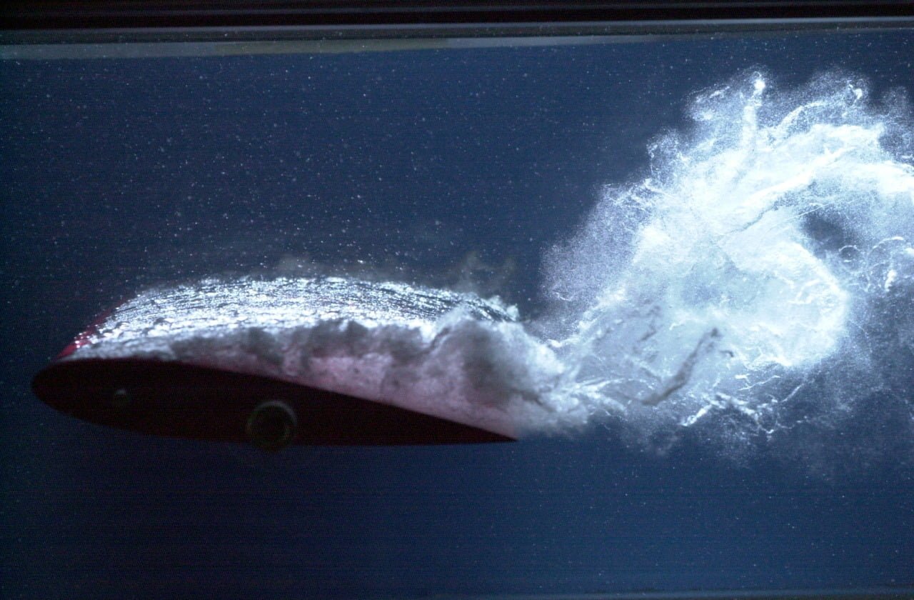
A cavitation-induced bubbly sheet flows over the upper surface of a hydrofoil in the image above. Cavitation can occur when local pressure in a liquid drops below the vapor pressure, causing a cavity to form. Due to its angle of attack, water flowing over the upper surface of the hydrofoil is accelerated. The high flow velocities and accompanying low pressures over the top of the hydrofoil produce cavitation bubbles which continue to flow over and off the surface. Because cavitation bubbles implode when the pressure again increases, they can cause serious damage to solid surfaces. This is why generating cavitation can damage propellers or shatter a bottle. (Photo credit: R. Arndt et al.)

Transonic Flow
In the transonic speed regime the overall speed of an airplane is less than Mach 1 but some parts of the flow around the aircraft break the speed of sound. The photo above shows a schlieren photograph of flow over an airfoil at transonic speeds. The nearly vertical lines are shock waves on the upper and lower surfaces of the airfoil. Although the freestream speed in the tunnel is less than Mach 1 upstream of the airfoil, air accelerates over the curved surface of airfoil and locally exceeds the speed of sound. When that supersonic flow cannot be sustained, a shock wave occurs; flow to the right of the shock wave is once again subsonic. It’s also worth noting the bright white turbulent flow along the upper surface of the airfoil after the shock. This is the boundary layer, which can often separate from the wing in transonic flows, causing a marked increase in drag and decrease in lift. Most commercial airliners operate at transonic Mach numbers and their geometry is specifically designed to mitigate some of the challenges of this speed regime. (Image credit: NASA; via D. Baals and W. Corliss)

Separating Flow
Flow separation occurs when a fluid is unable to flow smoothly around an object. In the case of the photo above, fog is being used to visualize flow around an airfoil at a large negative angle of attack. The incoming flow stagnates at a point on top of the airfoil, and streamlines on either side of that point split to move around the airfoil. Those on top are accelerated to high velocity, generating smooth, low-pressure flow over the aft section of the upper surface. On the other side of the stagnation point, however, the fog is trying to flow around the curve of the leading edge but the local pressure gradient is increasing, which slows the flow. Ultimately, it separates from the airfoil, creating a large region of recirculating, turbulent flow. When this effect occurs on the upper surface of a wing at a high (positive) angle of attack, it is called stall and causes a dramatic loss in lift. (Photo credit: Wikimedia/Smart Blade GmbH)