At small angles of attack, air flows smoothly around an airfoil, providing lifting force through the difference in pressure across the top and bottom of the airfoil. As the angle of attack increases, the lift produced by the airfoil increases as well but only to a point. Increasing the angle of attack also increases the adverse pressure gradient on the latter half of the top surface, visible here as an increasingly thick bright area. Over this part of the surface, the pressure is increasing from low to high–the opposite of the direction a fluid prefers to flow. Eventually, this pressure gradient grows strong enough that the flow separates from the airfoil, creating a recirculating bubble of air along much of the top surface. When this happens, the lift produced by the airfoil drops dramatically; this is known as stall.
Search results for: “airfoil”
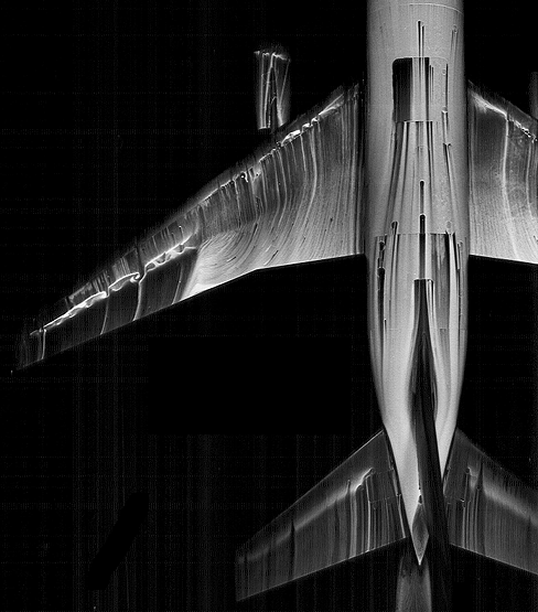
Flow Over Swept Wings
Flow over a swept wing behaves very differently than a straight fixed wing or an airfoil. Instead of flowing straight along the chord of the wing in a two-dimensional fashion, air is also directed along the wing, parallel to the leading edge. The above oil flow visualization on a swept wing airplane model shows this curvature of streamlines. As a result of this three-dimensional flow behavior, boundary layers on swept wings are subject to the crossflow instability, which manifests as co-rotating vortices aligned to within a few degrees of the streamlines. Triggering this boundary layer instability can lead to turbulence and higher drag for the aircraft.

Separation and Stall
This flow visualization of a pitching wind turbine blade demonstrates why lift and drag can change so drastically with angle of attack. When the angle the blade makes with the freestream is small, flow stays attached around the top and bottom surfaces of the blade. At large (positive or negative) angles of attack, the flow separates from the turbine blade, beginning at the trailing edge and moving forward as the angle of attack increases. The separated flow appears as a region of recirculation and turbulence. This is the same mechanism responsible for stall in aircraft. (Submitted by Bobby E)
Starting Vortices
Whenever a wing stops or starts in a fluid, it produces a vortex. This 2D numerical simulation shows an airfoil repeatedly starting and stopping, shedding a vortex each time. Note how the line of vortices drifts downward in the wake; this is an indication of downwash. (submitted by jessecaps)
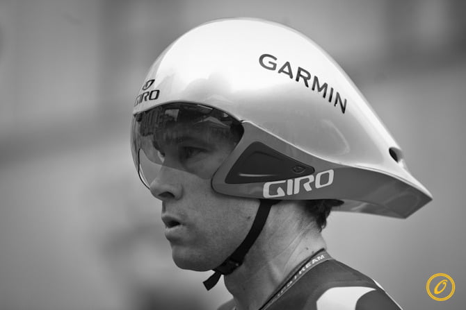
Tour de France Physics: Time Trials
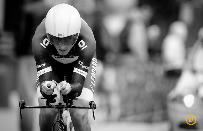
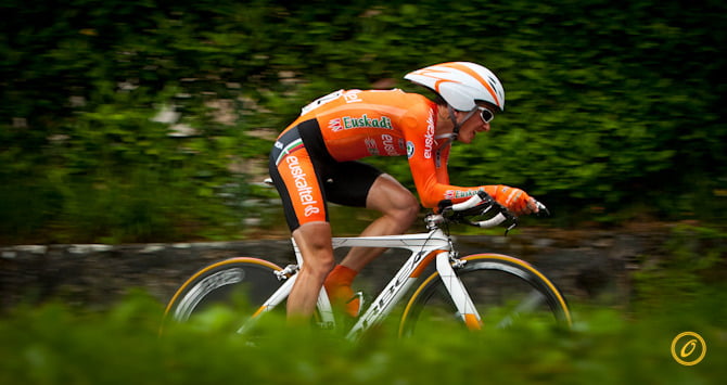
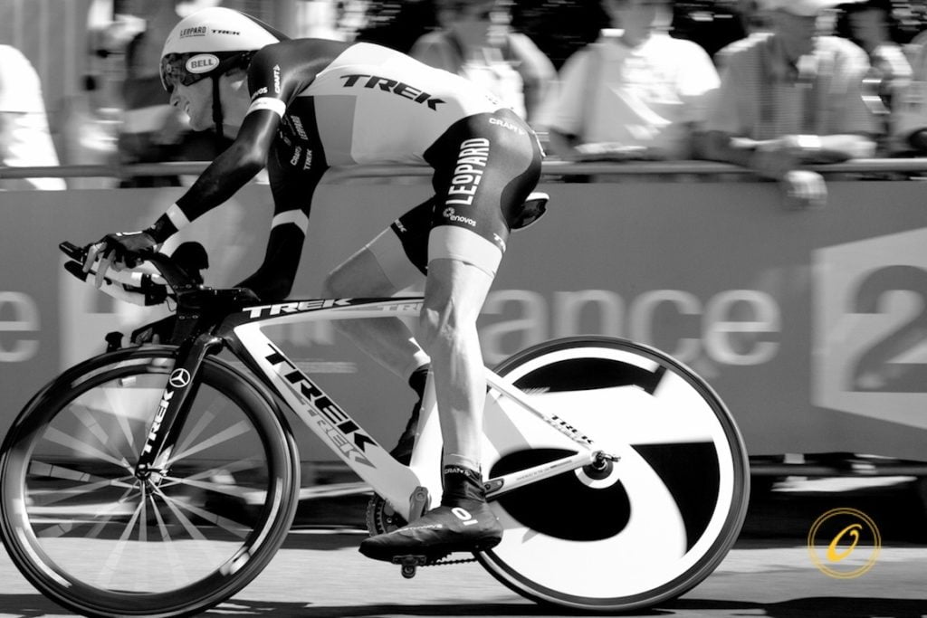
Unlike road stages in which cyclists can draft off one another to reduce drag, in the time trial a cyclist is on a solo race against the clock with nowhere to hide. As a result, the event features lots of technologies designed to reduce both pressure drag and skin friction on the cyclist. For time trials, cyclists wear skinsuits and shoe covers to eliminate any sources of flapping fabrics and to reduce skin friction. They ride bicycles designed to be as light and aerodynamic as possible. Instead of rounded tubing in the frames, these bikes consist of elongated airfoil profiles that direct air past and prevent separation that may increase pressure drag. The rims of their tires are wider and the back wheel is replaced with a disc wheel that allows no airflow aross the wheel. Like the airfoil tubing, these changes help prevent separation. Similarly, riders wear elongated helmets designed to be as aerodynamic as possible while the rider is in the “aero” position, with arms directed out over the wheels, head level, elbows tucked, and back flat. In wind tunnel tests, the rider best able to hold this position will experience the least drag. Even the addition or subtraction of a water bottle is not left to chance, with many time trial bikes designed to be more aerodynamic with a water bottle onboard (though you probably won’t catch the cyclists breaking their aero position to get a drink)! (Photos by Veeral Patel)
FYFD is celebrating the Tour de France with a weeklong exploration of the fluid dynamics of cycling. See previous posts on drafting in the peloton, and pacelining and echelons, and the art of the lead-out train.

Wright Brothers’ Wind Tunnel
A large part of the Wright Brothers’ ultimate success in creating the first powered heavier-than-air craft came as a result of work done in their homemade wind tunnel, shown above. In the aftermath of the failure of their 1901 Glider, the brothers decided that the lift and drag data they had used from Otto Lilienthal must be inaccurate. They built this wind tunnel and its force balances to measure lift and drag on two hundred different airfoils themselves and were rewarded with far more successful flights with their 1902 Glider, which led directly to the Wright Flyer in the following year. #
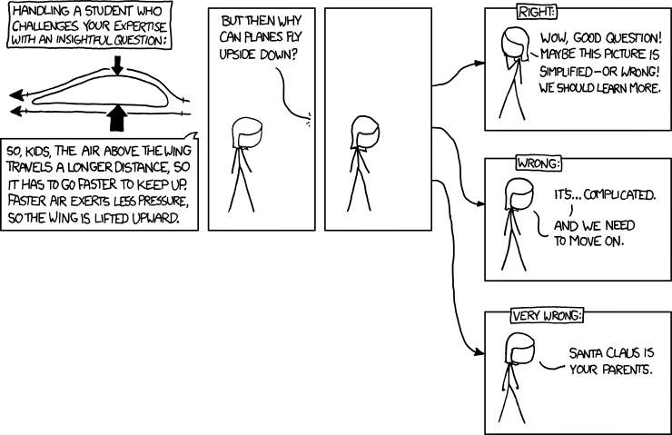
xkcd and Lift
xkcd identifies a very common misconception about how airfoils work! (via Vinnchan and jasonas14) #
How Wings Create Lift
One of the topics in fluid dynamics almost everyone has come across is the explanation of how airplanes produce lift. Using Bernoulli’s principle–which relates velocity and pressure–and a picture of an airfoil, your average science text will say that a bit of air going over the top of the airfoil has to travel farther than a bit of air going under the airfoil, and that, therefore, the air over the top travels faster than the air under the airfoil.
Unfortunately, this is misleading and, depending on the wording, outright wrong! The hidden assumption in this explanation is that air that goes over the top and air that goes under the bottom have to reach the trailing edge of the airfoil at the same time. But why would that be? (As one of my profs once said, “There is nothing in physics that says there is Conservation-Of-Who-You-Were-Sitting-Next-To-When-You-Started.”)
Take a look at the video above. It shows an airfoil in a wind tunnel using smoke visualization to show how the air moves. Around the 0:25 mark, the video slows to show a pulse of smoke traveling over the airfoil. What happens at the trailing edge? The smoke going over the top of the airfoil is well past the trailing edge by the time the smoke going under the airfoil reaches the trailing edge!
It’s true that air goes faster over the top of the airfoil than the bottom and that this causes a lower pressure on top of the airfoil (as Bernoulli tells us it should) and that this causes an upward force on the airfoil. But which causes which is something of a chicken-and-egg problem.
A more straightforward way, in my opinion, of explaining lift on an airplane is by thinking about Newton’s 3rd law: for every action, there is an equal and opposite reaction. Take a look at the air’s movement around the airfoil as the angle of attack is increased around 1:00 on the video. Just in front of the airfoil, the air is moving upward. Just after the airfoil, the air is pointed downward. A force from the airfoil has pushed the air down and changed its direction. By Newton’s 3rd law, this means that the air has pushed the airfoil up by the same amount. Voila! Lift!