
Yesterday we discussed some of the basic mechanics of a frisbee in flight. Although frisbees do generate lift similarly to a wing, they do have some unique features. You’ve probably noticed, for example, that the top surface of a frisbee has several raised concentric rings. These are not simply decoration! Instead the rings disrupt airflow at the surface of the frisbee. This actually creates a narrow region of separated flow, visible in region B on the left oil-flow image. Airflow reattaches to the frisbee in the image after the second black arc, and the boundary layer along region C remains turbulent and attached for the remaining length of the frisbee. Keeping the boundary layer attached over the top surface ensures low pressure so that the disk has plenty of lift and remains aerodynamically stable in flight. A smooth frisbee would be much harder to throw accurately because its flight would be very sensitive to angle of attack and likely to stall. (Image credits: J. Potts and W. Crowther; recommended papers by: V. Morrison and R. Lorentz)
Tag: boundary layer

Fluid Dynamics and the Nobel Prize

Last night marked the 2013 Ig Nobel Prize Award Ceremony, in which researchers are honored for work that “makes people LAUGH and then THINK”. Historically, the field of fluid dynamics has been well-represented at the Ig Nobels with some 13 winners across the fields of Physics, Chemistry, Mathematics, and–yes–Fluid Dynamics since the awards were introduced in 1991. This is in stark contrast to the awards’ more famous cousins, the Nobel Prizes.
Since the introduction of the Nobel Prize in 1901, only two of the Physics prizes have been fluids-related: the 1970 prize for discoveries in magnetohydrodynamics and the 1996 prize for the discovery of superfluidity in helium-3. Lord Rayleigh (a physicist whose name shows up here a lot) won a Nobel Prize in 1904, but not for his work in fluid dynamics. Another well-known Nobel laureate, Werner Heisenberg, actually began his career in fluid dynamics but quickly left it behind after his doctoral dissertation: “On the stability and turbulence of fluid flow.”
This is not to suggest that no fluid dynamicist has done work worthy of a Nobel Prize. Ludwig Prandtl, for example, revolutionized fluid dynamics with the concept of the boundary layer (pdf) in 1904 but never received the Nobel Prize for it, perhaps because the committee shied from giving the award for an achievement in classical physics. General consensus among fluid dynamicists is that anyone who can prove a solution for turbulence using the Navier-Stokes equation will likely receive a Nobel Prize in addition to a Millennium Prize. In the meantime, we carry on investigating fluids not for the chance at glory, but for the joy and beauty of the subject. (Image credits: Improbable Research and Wikipedia)

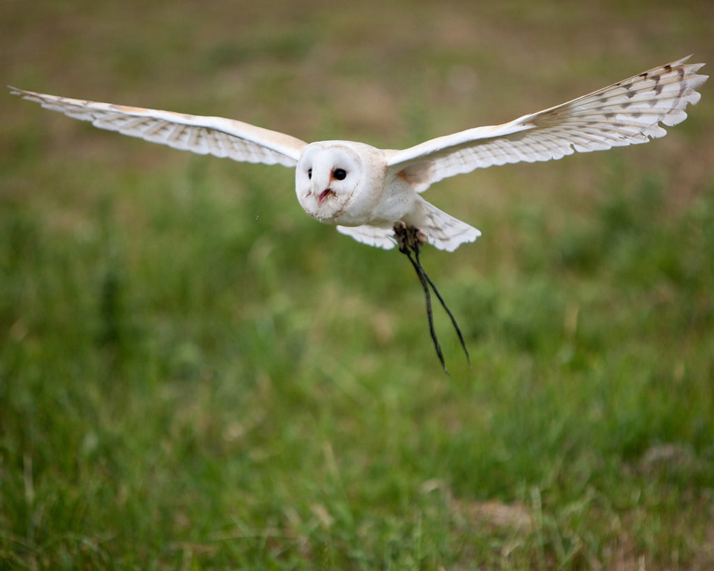
The Silence of Owls
Owls are nearly silent hunters, able to swoop down on their prey without the rush of air over their wings giving away their approach, thanks to several key features of their feathers. The trailing edge of their feathers–or any lifting body, like an airplane wing–are a particular source of acoustic noise due to the interaction of turbulence near the surface with the edge. Since owls are especially good at eliminating self-produced noise in a frequency range that overlaps human hearing, investigators want to learn what works for owls and apply to it aircraft. A recent theoretical analysis uses a simplified model of the feather as a porous, elastic plate. The researchers found that the combination of porosity with the elasticity of the trailing edge significantly reduced noise relative to a rigid edge. (Photo credit: N. Jewell; research credit: J. Jaworski and N. Peake)

Watching the Boundary Layer Go By
In experiments, it can be difficult to track individual fluid structures as they flow downstream. Here researchers capture this spatial development by towing a 5-meter flat plate past a stationary camera while visualizing the boundary layer – the area close to the plate. The result is that we see turbulent eddies evolving as they advect downstream. Despite the complicated and seemingly chaotic flow field, the eye is able to pick out patterns and structure, like the merging of vortices that lifts eddies up into turbulent bulges and the entrainment of freestream fluid into the boundary layer as the eddies turn over or collapse. It is also a great demonstration of how the Reynolds number relates to the separation of scales in a turbulent flow. Notice how much richer the variety of length-scale is for the higher Reynolds number case and how thoroughly this mixes the boundary layer. (Video credit: J. H. Lee et al.)

The Boundary Layer Visualized
Any time there is relative motion between a solid and a fluid, a small region near the surface will see a large change in velocity. This region, shown with smoke in the image above, is called the boundary layer. Here air flows from right to left over a spinning spheroid. At first, the boundary layer is laminar, its flow smooth and orderly. But tiny disturbances get into the boundary layer and one of them begins to grow. This disturbance ultimately causes the evenly spaced vortices we see wrapping around the mid-section of the model. These vortices themselves become unstable a short distance later, growing wavy before breaking down into complete turbulence. (Photo credit: Y. Kohama)
Spin-Up
With the Oscars just over, it seems like a good time for some movie-trailer-style fluid dynamics. This video shows a rotating water tank from the perspective of a camera rotating with the tank at 10 rpm. Initially, the tank and its contents are at rest. When the tank begins spinning, the fluid inside responds. Pink potassium permanganate crystals at the bottom of the tank show fluid motion as they dissolve, and food coloring is spread on the water’s surface to show motion there. Fluid near the edge of the tank reaches the tank’s rotational velocity fastest, due to friction with the wall, while fluid near the center of the tank takes longer to spin up to speed. This creates the spiral-galaxy-like shape in the dye. Eventually viscosity will transmit the effects of the wall’s motion even into the center of the tank. (Video credit: UCLA Spinlab)

Dye Flow
Fluid flow near a surface–inside the boundary layer–can often be unstable. This image shows one possible instability, formed when a cylinder is rotated back and forth about its longitudinal axis. This oscillation and the curvature of the cylinder destabilize flow in the boundary layer, forming vortices that line the cylinder. This particular behavior is called a Görtler instability. To visualize it, threads soaked in fluorescing dye have been embedded into slits in the cylinder. The cylinder is oscillated in a water tank and ultraviolet light is used to fluoresce the dye for the image. (Photo credit: Miguel Canals/University of Hawaii)

Supersonic Oil Flow Viz
This image shows oil-flow visualization of a cylindrical roughness element on a flat plate in supersonic flow. The flow direction is from left to right. In this technique, a thin layer of high-viscosity oil is painted over the surface and dusted with green fluorescent powder. Once the supersonic tunnel is started, the model gets injected in the flow for a few seconds, then retracted. After the run, ultraviolet lighting illuminates the fluorescent powder, allowing researchers to see how air flowed over the surface. Image (a) shows the flat plate without roughness; there is relatively little variation in the oil distribution. Image (b) includes a 1-mm high, 4-mm wide cylinder. Note bow-shaped disruption upstream of the roughness and the lines of alternating light and dark areas that wrap around the roughness and stretch downstream. These lines form where oil has been moved from one region and concentrated in another, usually due to vortices in the roughness wake. Image © shows the same behavior amplified yet further by the 4-mm high, 4-mm wide cylinder that sticks up well beyond the edge of the boundary layer. Such images, combined with other methods of flow visualization, help scientists piece together the structures that form due to surface roughness and how these affect downstream flow on vehicles like the Orion capsule during atmospheric re-entry. (Photo credit: P. Danehy et al./NASA Langley #)
Unsteady Rocket Nozzle
This numerical simulation gives a glimpse of flow inside an unsteady rocket nozzle. The nozzle is over-expanded, meaning that the exhaust’s pressure is lower than that of the ambient atmosphere. A slightly over-expanded nozzle causes little more than a decrease in efficiency, but if the nozzle is grossly over-expanded, the boundary layer along the nozzle wall can separate and induce major instabilities, as seen here. In the first segment of the video, turbulent structures along the nozzle wall boundary layer are shown; note how the boundary layer becomes very thick and turbulent after the primary shock wave (shown in gray). This is due to the flow separating near the wall. The second half of the video shows the unsteadiness this can create. The primary shock wave splits into two near the wall, creating a lambda shock wave, named for the shape of the lower case Greek letter. This shock structure is indicative of strong interaction between the boundary layer and shock wave. (Video credit: B. Olson and S. Lele)

London 2012: Cycling Physics


In no discipline of cycling is more emphasis placed on fluid dynamics than in the individual time trial. This event, a solo race against the clock, leaves riders no place to hide from the aerodynamic drag that makes up 70% or more of the resistance riders overcome when pedaling. Time trial bikes are designed for low drag and light weight over maneuverability, using airfoil-like shapes in the fork and frame to direct airflow around the bike and rider without separation, which creates an area of low pressure in the wake that increases drag. Riders maintain a position stretched out over the front wheel of the bike, with their arms close together. This position reduces the frontal area exposed to the flow, which is proportional to the drag a rider experiences.
Special helmets, some with strangely streamlined curves, are used to direct airflow over the rider’s head and straight along his or her back. Both helmets and skinsuits are starting to feature areas of dimpling or raised texturing. These function in much the same way as a golf ball; the texture causes the boundary layer, the thin layer of air near a surface, to become turbulent. A turbulent boundary layer is less susceptible to separating from the surface, ultimately leading to lower drag than would be observed if the boundary layer remained laminar. Wheels, skinsuits, gloves, shoe covers, and even the location of the brakes on the bike are all tweaked to reduce drag. In an event that can be decided by hundredths of a second between riders, every gram of drag counts. (Photo credits: Stefano Rellandini, POC Sports, Reuters, Paul Starkey, Louis Garneau)
FYFD is celebrating the Olympics by featuring the fluid dynamics of sports. Check out our previous posts on how the Olympic torch works, what makes a pool fast, the aerodynamics of archery, and the science of badminton.


