Search results for: “flow visualization”

  • CU Flow Vis 2019

    CU Flow Vis 2019

    I love when science and art come together, which is why I’ve long been a fan of the Flow Vis course at CU Boulder. Some of my earliest posts on FYFD date from previous editions of the course. Here are a few of my favorite images from the Fall 2019 class, from the top:

    •  Ferrofluid and India ink merge in this colorful photo. A magnet underneath the mixture on the left side causes the dark spikes of ferrofluid, but without magnetic influence, the ink and ferrofluid form cell-like droplets.
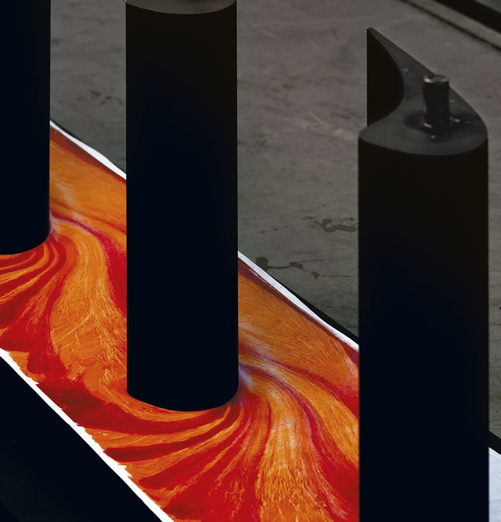
    • Although it looks like a shower head, this is actually fluorescent oobleck dripping through a strainer. A relatively long exposure time means that it’s impossible to tell whether the oobleck is falling in a fluid stream or broken-up chunks.
    • These colorful water droplets are sitting on a hydrophobic surface, hence their extremely rounded edges. I particularly like how this makes each one like a little lens for the light shining through them and into their shadows.
    • A thin layer of ferrofluid reacts to the magnet beneath. Gotta love those little streaks left behind the flow.

    For those in the Front Range area, the Flow Vis class will be showcasing their work on Saturday, December 14th at the Fiske Planetarium. Snacks are at 4:30 pm and the show starts at 5 pm. For those not nearby, you can peruse the art from this semester and previous ones at your leisure online. (Image credits: colorful ferrofluid – R. Drevno; falling oobleck – A. Kumar; droplets – A. Barron; macro ferrofluid – A. Zetley)

  • Sunset Flow

    Sunset Flow

    Day and night mix in this flow visualization of watercolor pigments and ferrofluid. The former, as suggested by their name, are water-based, whereas ferrofluids typically contain an oil base. This means the two fluids are immiscible. Like oil and vinegar in salad dressing, the only way to mix them is to break one into tiny droplets floating in the other. This is what happens near their boundary, where brightly-colored paint droplets float in a network of dark channels. To the right, the paint and ferrofluid have been swirled around to create viscous mixing patterns among the paint colors with occasional intrusions of thin ferrofluid fingers. (Image credit: G. Elbert)

  • Delta Wing Flow Viz

    Delta Wing Flow Viz

    Designing new aerodynamic vehicles typically requires a combination of multiple experimental and numerical techniques. The photo above shows a model for an unmanned flying wing-type vehicle. Here it’s tested in a water tunnel with dye introduced to the flow to highlight different areas. The model is at a high angle of attack (18 degrees) relative to the oncoming flow. This puts it in danger of flow separation and stall, the point where a wing experiences a drastic loss in lift. The smooth flow over the front of the model indicates it hasn’t reached this point yet, but notice how both the green and red dyes are separating from the model and becoming very turbulent over the back of the wing. If the model were pushed to an even higher angle of attack, that separation point would move further forward, bringing stall that much closer. (Image credit: L. Erm and J. Drobik; research credit: R. Cummings and A. Schütte)

  • Rheoscopic Flow Vis

    Rheoscopic Flow Vis

    One of the great challenges in visualizing fluid flows is the freedom of movement. A fluid particle – meaning some tiny little bit of fluid we want to follow – is generally free to move in any direction and even change its shape (but not mass). This makes tracking all of those changes difficult, and it’s part of why there are so many different techniques for flow visualization. The technique an experimenter uses depends on the information they hope to get.

    Often a researcher may want to know about fluid velocity in two or more directions, which can require multiple camera angles and more than one laser sheet illuminating the flow. An alternative to such a set-up is shown above. The injected fluid – known as a rheoscopic fluid – contains microscopic reflective particles, in this case mica, that are asymmetric in shape. Imagine a tiny rod, for example. By illuminating the rod from different directions with different colors of light, you can determine the particle’s orientation based on the color it reflects. Since the orientation of the particle depends on the surrounding flow, you can infer how the flow moves. (Image credit and submission: J. C. Straccia; research link: V. Bezuglyy et al.)

  • Flow in a Turbine

    Flow in a Turbine

    Fluid flows are complex, complicated, and ever-changing. Researchers use many techniques to visualize parts of a flow, which can help make what’s happening clearer. One technique, shown above, uses oil and dye to visualize flow at the surface. The vertical, black, airfoil-shaped pieces are stators, stationary parts within a turbine that help direct flow. After painting the stator mount surface with a uniform layer of oil, the model can be placed in a wind tunnel (or turbine) and exposed to flow. Air moving around the stators drags some of the oil with it, creating the darker and lighter streaks seen here. Notice how the lines of oil turn sharply around the front of the stator and bunch up near its widest point. Those crowded flow lines tell researchers that the air moves quickly around this corner. (Image credit: D. Klaubert et al., source)

  • Flow Above the Treetops

    Flow Above the Treetops

    As this smoke visualization shows, trees have a significant impact on airflow around them. Flow in the image is from left to right. On the left, the upstream air is traveling in smooth, laminar lines that are quickly disrupted as the flow moves into the trees. After the first shorter trees, flow inside the wooded area has been broken up and slowed. Above the canopy, the smoke streaklines have also slowed and become more turbulent. Understanding how wind and trees interact is important in a variety of applications, including when adding renewable energy options to buildings and when predicting the spread of forest fires. (Image credit: W. Frank et al.)

  • Featured Video Play Icon

    Visualizing Flow with Snowfall

    One of the challenges in engineering and operating wind turbines is that full-scale turbines rarely behave as predicted in smaller-scale laboratory experiments and simulations. One way to reconcile these differences (and discover what our experiments and simulations are missing) is to take the experiments out into the field. One research group has done this by using snowfall to visualize the flow around wind turbines. In this video, they share some of their observations, which include interactions of tip vortices with one another and with the vortex from the tower. My favorite part starts around 1:50 where you can observe tip vortices leap-frogging one another behind the wind turbine! (Video credit: Y. Liu et al.)

  • Lava Flowing

    Lava Flowing

    Lava flows like these Hawaii’an ones are endlessly mesmerizing. This type of flow is gravity-driven; rather than being pushed by explosive pressure, the lava flows under its own weight and that of the lava upstream. In fact, fluid dynamicists refer to this kind of flow as a gravity current, a term also applied to avalanches, turbidity currents, and cold drafts that sneak under your door in the wintertime. How quickly these viscous flows spread depends on factors like the density and viscosity of the lava and on the volume of lava being released at the vent. As the lava cools, its viscosity increases rapidly, and an outer crust can solidify while molten lava continues to flow beneath. Be sure to check out the full video below for even more gorgeous views of lava.  (Image/video credit: J. Tarsen, source; via J. Hertzberg)

  • Flow Around a Delta Wing

    Flow Around a Delta Wing

    Colorful streaks of dye wrap like ribbons along the leading edge of a delta wing. At an angle of attack, this triangular wing forms a set of vortices that run along its edge, providing much of the low pressure–and therefore lift–on the upper surface of the wing. In contrast, the red streaks of dye in the middle of the wing demonstrate clean, laminar flow. Highly swept delta wings are popular for aircraft traveling at supersonic speeds, but they can also work well subsonically, as shown here. For more incredible and beautiful examples of flow visualizations by Henri Werlé, check out his 1974 film Courants et couleurs. (Photo credit: H. Werlé; via eFluids)

  • Jumps in Stratified Flows

    Jumps in Stratified Flows

    One of the factors that complicates geophysical flows is that both the atmosphere and the ocean are stratified fluids with many stacked layers of differing densities. These variations in density can generate instabilities, trap rising or sinking fluids, and transmit waves. The animations above show flow over two ridges with dye visualization (top), velocity (middle), and contours of density (bottom). The upstream influence of the left ridge creates a smooth, focused flow that quickly becomes turbulent after the crest. The jet rebounds as a turbulent hydraulic jump before slowing again upstream of the second ridge. Like the first ridge, the second ridge also generates a hydraulic jump on the lee side. Clearly both stratification and the local topography play a big role in how air moves over and between the ridges. If prevailing winds favor these kinds of flows, it can help generate local microclimates. (Image credit and submission: K. Winters, source videos)