Search results for: “drag”

  • Reader Question: Submarines

    Reader Question: Submarines

    Reader elimik asks:

    Why do modern submarines have round bows instead of pointy ones, like the early WWII ones?

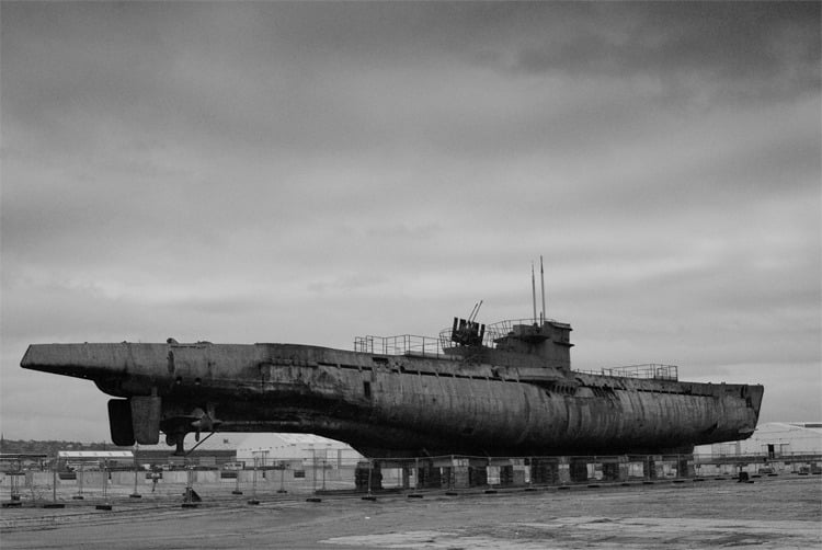
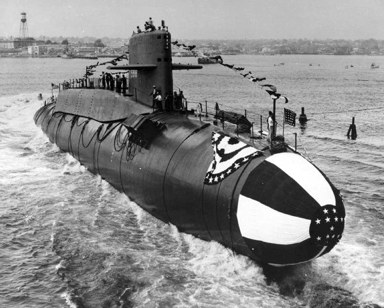
    Interestingly, there are more factors that affect this design choice than I originally thought! Perhaps the biggest factor, though, is propulsion. Although early submarines ran through several forms of propulsion from human power to steam, by World War II many subs were driven by diesel-power on the surface and relied on battery power when submerged. Power limitations meant that submarines of that era did most of their travel while at the surface, not underwater. As a result, the ships had better control and decreased drag with a pointed bow similar to that of a surface ship. It wasn’t until the advent of the nuclear-powered submarine that it became practical for submarines to spend most of their time submerged. Once fully-underwater travel was feasible (and, indeed, preferable), many subs transitioned to a blunter, rounded bow that’s more hydrodynamic underwater–and simultaneously more problematic control-wise when moving on the surface.

    Another factor separating WW-era submarines and modern subs is the depth to which they submerge. The deeper a submarine dives, the greater the pressure it must withstand. Rounded or cylindrical shapes make much better pressure vessels because they distribute pressure evenly around a surface. Historically, many subs have balanced control and hydrodynamics against pressure requirements by having two hulls, an outer one for cutting through surface waters and an inner cylindrical one that bears the brunt of the hydrostatic pressure. As we developed stronger materials, though, submarines have achieved greater depths. The German Type VII submarine, the most common U-boat of WWII, had a test depth of 230 m, whereas today’s Los-Angeles-class U.S. submarine can operate at 290 m. (Each 10 meters of depth adds about one atmosphere’s worth of pressure.) The combination of nuclear power for subsurface propulsion and stronger materials that allow deeper dives enables many modern submarines to have a single hull–the rounded hydrodynamic and pressure-resistant bow we commonly see.  (Image credits: U534 by P. Adams and USS George Washington by U.S. Navy)

  • Featured Video Play Icon

    Half Vortex Rings

    Vortices are one of the most common structures in fluid dynamics. In this video, Dianna from Physics Girl explores an unusual variety of vortex you can create in a pool. Dragging a plate through the water at the surface creates a half vortex ring, which can be tracked either by the surface depressions created or by using food dye for visualization. Vortex rings are quite common, but a half vortex ring is not. The reason is that, ignoring viscous effects, a vortex filament cannot end in a fluid. The vortex must close back on itself in a loop, or, like the half vortex ring, the ends of the vortex must lie on the fluid boundary. It is possible to break vortex lines like those in smoke rings, but the lines will reattach, creating new vortex rings–just as they do in these vortex knots. (Video credit: Physics Girl; submitted by Tom)

  • Turbine Blade Separation

    [original media no longer available]

    Maintaining consistent air flow along the contours of an object is key to aerodynamic efficiency. When air flow separates or forms a recirculation zone, the drag increases and efficiency drops. On wind turbine blades, flow often separates on the root end of the blade near its attachment point. This behavior is apparent in the video above at 0:34. The tufts in the foreground on the turning blade flap and flutter with no clear pattern because the air flow has separated from the surface. In the subsequent clip, a line of vortex generators has been attached near the leading edge of the blade. These structures–also commonly seen on airplanes–trail vortices behind them, mixing the flow and generating a turbulent boundary layer which is better able to resist flow separation. The effect on the flow is clear from the tufts, most of which now point in a consistent direction with little to no fluttering, indicating that the air flow has remained attached. (Video credit: Smart Blade Gmbh/Technische Universität Berlin)

    (Source: /)
  • Hovering

    Hovering

    Designer Eleanor Lutz used high-speed video of five different flying species to create this graphic illustrating the curves swept out in their wingbeats. The curves are constructed from 15 points per wingbeat and are intended more as art than science, but they’re a fantastic visualization of several important concepts in flapping flight. For example, note the directionality of the curves as a whole. If you imagine a vector perpendicular to the wing curves, you’ll notice that the bat, goose, and dragonfly would all have vectors pointing forward and slightly upward. In contrast, the moth and hummingbird would have vectors pointing almost entirely upward. This is because the moth and hummingbird are hovering, so their wing strokes are oriented so that the force produced balances their weight. The bat, goose, and dragonfly are all engaged in forward flight, so the aerodynamic force they generate is directed to counter their weight and to provide thrust. (Image credit: E. Lutz; via io9)

  • Transonic Flow

    Transonic Flow

    In the transonic speed regime the overall speed of an airplane is less than Mach 1 but some parts of the flow around the aircraft break the speed of sound. The photo above shows a schlieren photograph of flow over an airfoil at transonic speeds. The nearly vertical lines are shock waves on the upper and lower surfaces of the airfoil. Although the freestream speed in the tunnel is less than Mach 1 upstream of the airfoil, air accelerates over the curved surface of airfoil and locally exceeds the speed of sound. When that supersonic flow cannot be sustained, a shock wave occurs; flow to the right of the shock wave is once again subsonic. It’s also worth noting the bright white turbulent flow along the upper surface of the airfoil after the shock. This is the boundary layer, which can often separate from the wing in transonic flows, causing a marked increase in drag and decrease in lift. Most commercial airliners operate at transonic Mach numbers and their geometry is specifically designed to mitigate some of the challenges of this speed regime.  (Image credit: NASA; via D. Baals and W. Corliss)

  • Featured Video Play Icon

    Seahorse Hunting

    Those who have observed the languid pace of seahorses or seadragons swimming might think these fish only hunt slow prey. In fact, the tiny crustaceans on which they feed are extremely quick, capable of velocities over 500 body lengths per second. Instead of speed, the seahorse relies on stealth to capture its prey, as shown in the holographic video above. Seahorses use a pivot method to feed, simultaneously shifting their snouts up and sucking water in to catch their target. But this method of feeding only works for distances of about 1 mm. To get that close in the first place, the seahorse must approach its prey without alerting it. Researchers found that both the seahorse’s head shape and its natural posture create a hydrodynamic quiet zone just off the seahorse’s snout, directly in its strike zone. Fluid velocity and deformation rates in this region are significantly lower than those around the rest of the seahorse’s face when it moves, allowing the fish to sneak up on its prey. These adaptations are remarkably effective, too; the researchers observed that the seahorses were able to position themselves within 1mm of their prey without alerting them 84% of the time. (Video credit: B. Gemmell et al.; via Discover)

  • Frisbee Physics

    Frisbee Physics

    Frisbees are a popular summertime toy, but they involve some pretty neat physics, too. Two key ingredients to their long flight times are their lift generation and spin. A frisbee in flight behaves very much like a wing, generating lift by flying at an angle of attack. This angle of attack and the curvature of the disk rim cause air to accelerate over the top of the leading edge. Airflow over the top of the disk is faster than that across the bottom;  thus, pressure is lower over the top of the frisbee and lift is generated. Aerodynamic lift and drag aren’t enough to keep the frisbee aloft long, though. Spin matters, too. If the frisbee is launched without spin, gravity acts on it through its center of mass, but lift and drag act through a point off-center because lift tends to be higher on the front of the disk than the back. This offset between gravitational forces and aerodynamic forces creates a torque that tends to flip the frisbee. By spinning the frisbee, the thrower gives it a high angular momentum acting about its spin axis. Now instead of flipping the disk, the torque caused by the offset forces just tips the angular momentum vector slightly. Physically, this is known as spin stabilization or gyroscopic stability. Tomorrow we’ll take a closer look at airflow over the frisbee.  (Image credit: A. Leibel and C. Pugh, source video; recommended papers by: V. Morrison and R. Lorentz)

  • Sharkskin Fluid Dynamics

    Sharkskin Fluid Dynamics

    Sharks have evolved some incredible fluid dynamical abilities. Instead of scales, their skin is covered in microscopic structures called denticles. To give you a sense of size, each denticle in the black and white image above is about 100 microns across. Denticles are asymmetric and overlap one another, creating a preferential flow direction along the shark. When water tries to move opposite the preferred direction, the denticles will bristle, like in the animation above. The bristled denticles form an obstacle for the reversed flow without any effort on the shark’s part. Since local flow reversal is an early sign of separation, researchers theorize that this bristling tendency prevents flow along the shark’s skin from separating. Keeping flow attached, especially along the shark’s tail, is vital not only to the shark’s agility but to keeping its drag low. Researchers have even begun 3D printing artificial shark skin to try and harness the animal’s hydrodynamic prowess. For much more shark-themed science, be sure to check out this week’s “Several Consecutive Calendar Days Dedicated to Predatory Cartilaginous Fishes” video series by SciShow, It’s Okay to be Smart, The Brain Scoop, Smarter Every Day, and Minute Physics. (Image credits: J. Oeffner and G. Lauder; A. Lang et al.; original video; jidanchaomian)

  • Reader Question: Winglets

    Reader Question: Winglets

    Reader tvargo writes:

    First off… love your blog! I know very little about physics, but love reading about it. Could you potentially explain what the little upturned ends of wings do? looking on wikipedia is see this: “There are several types of wingtip devices, and although they function in different manners, the intended effect is always to reduce the aircraft’s drag by partial recovery of the tip vortex energy.” huh?

    Thanks! That’s a great question. Winglets are very common, especially on commercial airliners. To understand what they do, it’s helpful to first think about a winglet-less airplane wing. Each section of the wing produces lift. For a uniform, infinite wing, the lift produced at each spanwise location would be the same. In reality, though, wings are finite and wingtip vortices at their ends distort the flow. The vortices’ upward flow around the ends of the wing reduces the lift produced at the wing’s outermost sections, making the finite wing less efficient (though obviously more practical) than an infinite wing.

    Adding a winglet modifies the end conditions, both by redirecting the wingtip vortices away from the underside of the wing and by reducing the strength of the vortex. Both actions cause the winglet-equipped wing to produce more lift near the outboard ends than a wing without winglets.

    But why, you might ask, does the Wikipedia explanation talk about reducing drag? Since a finite wing produces less lift than an infinite one, finite wings must be flown at a higher angle of attack to produce equivalent lift. Increasing the angle of attack also increases drag on the wing. (If you’ve ever stuck a tilted hand out a car window at speed, then you’re familiar with this effect.) Because the winglet recovers some of the lift that would otherwise be lost, it allows the wing to be flown at a lower angle of attack, thereby reducing the drag. Thus, overall, adding winglets improves a wing’s efficiency. (Photo credit: C. Castro)

  • Turbojet Engines

    [original media no longer available]

    GE has a great new video with a straightforward explanation of the turbojet and the turbofan engines. The simplest description of the engines–suck, squeeze, bang, blow–sounds like a euphemism but it’s fairly accurate. The engines draw in air, compress it by making it flow through a series of small rotating blades, add fuel and combust the mixture, pull out energy through a turbine, and then blow the high-speed exhaust out the back to generate thrust. The thrust is key because it’s the force that overcomes drag on the plane and also generates the speed needed to create lift. There are two ways to significantly increase thrust: a) increase the mass flow rate of air through the engine, and/or b) increase the exhaust velocity. The turbojet engine draws in smaller amounts of air but generates very high exhaust velocities. The turbofan is today’s preferred commercial aircraft engine because it can generate thrust more efficiently at the desired aircraft velocity. The turbofan essentially has a turbojet engine in its center and is surrounded by a large air-bypass. Most of the air passing through the engine flows through the bypass and the fan. This increases its velocity only slightly, but it means that the engine accelerates much larger amounts of air without requiring much larger amounts of fuel. As an added bonus, the lower exhaust velocities of the turbofan engine make it much quieter in operation. (Video credit: General Electric)