Tag: oil flow visualization

  • Featured Video Play Icon

    Seeing the Flow

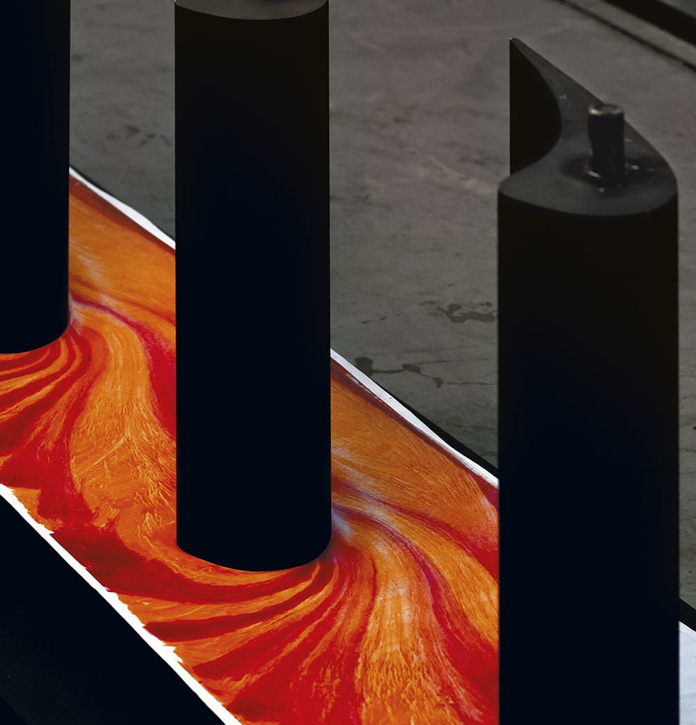
    Experimentalists often need a sense for the overall flow before they can decide where to measure in greater detail. For such situations, flow visualization techniques are a powerful tool since they provide quick ways to see and compare flows.

    Here, researchers paint a viscous oil atop their flying wing model and observe how the oil moves once the air flow starts up. This oil flow visualization shows the large-scale shifts in how air flows over the craft as the angle of attack increases. The disadvantage is that these techniques often give only a qualitative sense of the flow. But they can allow experimentalists to test many different conditions to decide which specific cases they should examine quantitatively. (Image and video credit: V. Kumar et al.)

  • Flow on Commercial Wings

    Flow on Commercial Wings

    Even in an era of supercomputers, there is a place for quick and dirty methods of flow visualization. Here we see a model of a swept wing like those seen on many commercial airliners. It was painted with a layer of fluorescent oil, then placed in a wind tunnel and subjected to flow. As air blows across the model, it moves the oil, leaving behind streaks that show how air near the surface moves. 

    We can see, for example, that near the fuselage, the air flows mostly front to back across the wing. That’s what we expect, especially for a wing generating lift. But further out on the wing, the flow moves mostly along the wing, not across it. There’s also a distinctive line running just a short ways behind the leading edge on this outer section of wing. It looks as though air flowing over the wing separated at this point, leaving disordered and unhelpful flow behind. It’s likely that the model was tested at an angle of attack where the outer section of the wing was beginning to stall. (Image credit: ARA)

  • Soap Film Evolution

    Soap Film Evolution

    The beautiful colors of a soap film reflect its variations in thickness. As a film drains and evaporates, it turns to shades of gray and black as it gets thinner. More than fifty years ago, one scientist proposed a free-energy-based explanation for how such ultrathin films might evolve. But it’s taken another half a century for experimental techniques to reach a point where the thickness of these ultrathin films could be measured well enough to test that theory. The new mechanism, known as spinodal stratification, has been observed in both vertical films (top) and foam (bottom) but has so far not been observed in any horizontal configuration, suggesting that buoyant effects are likely important, too. (Image and research credit: S. Yilixiati et al.; submitted by James S.)

  • Flow in a Turbine

    Flow in a Turbine

    Fluid flows are complex, complicated, and ever-changing. Researchers use many techniques to visualize parts of a flow, which can help make what’s happening clearer. One technique, shown above, uses oil and dye to visualize flow at the surface. The vertical, black, airfoil-shaped pieces are stators, stationary parts within a turbine that help direct flow. After painting the stator mount surface with a uniform layer of oil, the model can be placed in a wind tunnel (or turbine) and exposed to flow. Air moving around the stators drags some of the oil with it, creating the darker and lighter streaks seen here. Notice how the lines of oil turn sharply around the front of the stator and bunch up near its widest point. Those crowded flow lines tell researchers that the air moves quickly around this corner. (Image credit: D. Klaubert et al., source)

  • The Challenges of Micro Air Vehicles

    The Challenges of Micro Air Vehicles

    Interest in micro-aerial vehicles (MAVs) has proliferated in the last decade. But making these aircraft fly is more complicated than simply shrinking airplane designs. At smaller sizes and lower speeds, an airplane’s Reynolds number is smaller, too, and it behaves aerodynamically differently. The photo above shows the upper surface of a low Reynolds number airfoil that’s been treated with oil for flow visualization. The flow in the photo is from left to right. On the left side, the air has flowed in a smooth and laminar fashion over the first 35% of the wing, as seen from the long streaks of oil. In the middle, though, the oil is speckled, which indicates that air hasn’t been flowing over it–the flow has separated from the surface, leaving a bubble of slowly recirculating air next to the airfoil. Further to the right, about 65% of the way down the wing, the flow has reattached to the airfoil, driving the oil to either side and creating the dark line seen in the image. Such flow separation and reattachment is common for airfoils at these scales, and the loss of lift (and of control) this sudden change can cause is a major challenge for MAV designers. (Image credit: M. Selig et al.)

  • Oil Flow Viz

    Oil Flow Viz

    Fluorescent oil sprayed onto a model in the NASA Langley 14 by 22-Foot Subsonic Wind Tunnel glows under ultraviolet light. Airflow over the model pulls the initially even coat of oil into patterns dependent on the air’s path. The air accelerates around the curved leading edge of the model, curling up into a strong lifting vortex similar to that seen on a delta wing. At the joint where the wings separate from the body those lifting vortices appear to form strong recirculation zones, as evidenced by the spiral patterns in the oil. Dark patches, like those downstream of the engines could be caused by an uneven application of oil or by areas of turbulent flow, which has larger shear stress at the wall than laminar flow and thus applies more force to move the oil away. Be sure to check out NASA’s page for high-resolution versions of the photo. (Photo credit: NASA Langley/Preston Martin; via PopSci)

  • Streamlines in Oil

    Streamlines in Oil

    Bernoulli’s principle describes the relationship between pressure and velocity in a fluid: in short, an increase in velocity is accompanied by a drop in pressure and vice versa. This photo shows the results left behind by oil-flow visualization after subsonic flow has passed over a cone (flowing right to left). The orange-pink stripes mark the streamlines of air passing around the Pitot tube sitting near the surface. The streamlines bend around the mouth of probe, leaving behind a clear region. This is a stagnation point of the flow, where the velocity goes to zero and the pressure reaches a maximum. Pitot tubes measure the stagnation pressure, and, when combined with the static pressure (which, counterintuitively, is the pressure measured in the moving fluid), can be used to calculate the velocity or, for supersonic flows, the Mach number of the local flow. (Photo credit: N. Sharp)

  • Reader Question: Does Flow Viz Alter Flow?

    Reader Question: Does Flow Viz Alter Flow?

  • Featured Video Play Icon

    Effects of Hills on Flow

    Hills and other topology can have interesting and complex effects on a flowfield. With the FAITH experiment, NASA has been investigating an axisymmetric model hill using a combination of experimental methods. The video above shows flow visualization over the hill in a water channel using dye injection both upstream and downstream of the model. They’ve also done wind tunnel tests with oil-flow visualization, particle-image velocimetry, pressure sensitive paint and other measurement techniques. There are nice photos of some of these by Rob Bulmahn. By combining qualitative and quantitative flow measurement techniques, the researchers are able to capture many different aspects of the flow, which can then be shared and compared with other groups’ works. (Video credit: NASA Ames Research Center)

  • Supersonic Oil Flow Viz

    Supersonic Oil Flow Viz

    This image shows oil-flow visualization of a cylindrical roughness element on a flat plate in supersonic flow. The flow direction is from left to right. In this technique, a thin layer of high-viscosity oil is painted over the surface and dusted with green fluorescent powder. Once the supersonic tunnel is started, the model gets injected in the flow for a few seconds, then retracted. After the run, ultraviolet lighting illuminates the fluorescent powder, allowing researchers to see how air flowed over the surface. Image (a) shows the flat plate without roughness; there is relatively little variation in the oil distribution. Image (b) includes a 1-mm high, 4-mm wide cylinder. Note bow-shaped disruption upstream of the roughness and the lines of alternating light and dark areas that wrap around the roughness and stretch downstream. These lines form where oil has been moved from one region and concentrated in another, usually due to vortices in the roughness wake. Image © shows the same behavior amplified yet further by the 4-mm high, 4-mm wide cylinder that sticks up well beyond the edge of the boundary layer. Such images, combined with other methods of flow visualization, help scientists piece together the structures that form due to surface roughness and how these affect downstream flow on vehicles like the Orion capsule during atmospheric re-entry. (Photo credit: P. Danehy et al./NASA Langley #)