Tag: boundary layer separation

  • Tokyo 2020: Baseball Aerodynamics

    Tokyo 2020: Baseball Aerodynamics

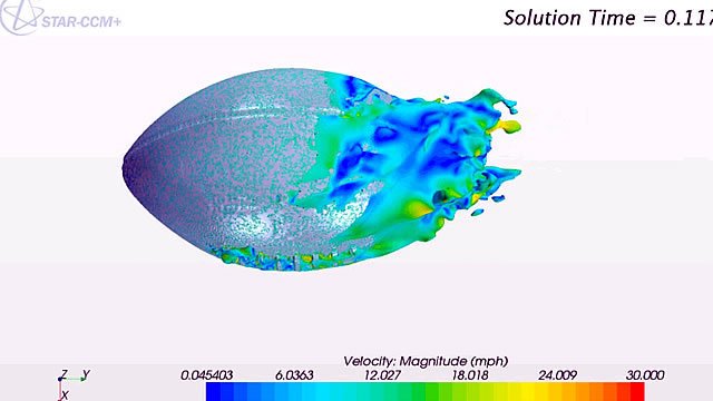
    For a long time, people thought baseball aerodynamics were simply a competition between gravity and the Magnus effect caused when a ball is spinning. But the seams of a baseball are so prominent that they, too, have a role to play. Here’s a baseline image of flow around a non-spinning baseball:

    An non-spinning baseball with a straight, unaltered wake.

    As in our previous post on golf, the colors indicate the direction of vorticity but don’t matter much to us here. What’s important is that the wake behind the ball is straight, indicating that there is no additional force beyond gravity and drag acting on the ball. Contrast this to the spinning baseball below:

    Flow around a baseball spinning clockwise.

    This ball is spinning in a clockwise motion, which causes flow to separate from the ball earlier on the advancing (bottom) side and later on the retreating (top) side. As a result, the wake is tilted downward. This indicates an upward force on the ball, caused by the Magnus effect.

    But what if the seams fall in a place where they affect the flow? Here’s another baseball that’s not spinning:

    Flow around a non-spinning baseball with a seam-shifted wake caused by early separation on the top surface of the baseball.

    Notice that seam sitting just past the widest point on the top of the baseball. Flow around that wide point (called the shoulder) is very sensitive to disturbances essentially because the boundary layer is just barely hanging on to the ball. The blue arrow marks where the boundary layer separates from the ball on the top, which takes place earlier than the flow separation on the bottom, marked by the red arrow. As a result, the wake of the ball is tilted upward, indicating a downward force on the ball. The researchers who first proved this effect call it a seam-shifted wake, and it turns out to be a very common effect in baseball. They’ve got a great blog dedicated to baseball aerodynamics where you can learn tons more if you’re interested. (Image credit: top – Pixabay, others – B. Smith; research credit: B. Smith; see also Baseball Aerodynamics)

    Today wraps up our Olympic coverage, but if you missed our earlier posts, you can find them all here.

  • The Telstar 18

    The Telstar 18

    Every four years, Adidas creates a newly designed ball for the World Cup. This year’s version is the Telstar 18, which features six glued panels (no stitching!) with a slightly raised texture. That subtle roughness is an important feature for the ball’s aerodynamics. It helps ensure that flow around the ball will become turbulent at relatively low speeds. Some previous designs, notably the 2010 Jabulani, were so smooth that flow near the ball would not become turbulent until much higher speeds. In fact, one side of the ball might have laminar flow while the other was turbulent, causing the ball to wobble and misbehave. To learn more about World Cup aerodynamics and the importance of a little surface roughness to the ball’s behavior, check out the Physics Girl video below.    (Image credit: Adidas; via APS News; video credit: Physics Girl)

  • Withstanding Windstorms

    Withstanding Windstorms

    Saguaro cacti can grow 15 meters tall, and despite their shallow root systems can withstand storm winds up to 38 meters per second without being blown over. Grooves in the cacti’s surface may contribute to its resilience, by adding structural support and/or through reducing aerodynamic loads. The latter theory mirrors the concept of dimples on a golf ball; namely, grooves create turbulence in the flow near the cactus, which allows air flow to track further around the cactus before separating. The result is less drag for a given wind speed than a smooth cactus would experience.

    Indeed, recent experiments on a grooved cylinder with a pneumatically-controlled shape showed exactly that; the morphable cylinder’s drag was consistently significantly lower than fixed samples. Cacti do change their shapes somewhat as their water content changes, but they don’t have the ability for up-to-the-minute alterations. Nevertheless, their adaptations can inspire engineered creations that morph to reduce wind impact. (Image credit: A. Levine; research credit: M. Guttag and P. Reis)

  • Featured Video Play Icon

    Perching Physics

    Compared to birds, manmade aircraft tend to be quite limited and inelegant. Fixed-wing aircraft, for example, require long, flat areas for take-off and landing, whereas birds of all sizes are adept at maneuvers like perching. This video examines the perching behaviors of large birds and extends the physics to a small unmanned aerial vehicle (UAV). As a bird approaches a perching location, it pitches its body and wings upward. This places the bird in what’s known as deep stall, where air flowing over the upper surface of the wing separates just after the leading edge. This move dramatically increases drag on the bird, slowing it for landing. At the same time, the speed of the pitch maneuver generates a vortex on the wing that helps the bird maintain lift despite the drop in speed. With the help of both forces, the bird can make a graceful, controlled landing in only a short distance. (Video credit: J. Mitchell et. al.)

  • The Challenges of Micro Air Vehicles

    The Challenges of Micro Air Vehicles

    Interest in micro-aerial vehicles (MAVs) has proliferated in the last decade. But making these aircraft fly is more complicated than simply shrinking airplane designs. At smaller sizes and lower speeds, an airplane’s Reynolds number is smaller, too, and it behaves aerodynamically differently. The photo above shows the upper surface of a low Reynolds number airfoil that’s been treated with oil for flow visualization. The flow in the photo is from left to right. On the left side, the air has flowed in a smooth and laminar fashion over the first 35% of the wing, as seen from the long streaks of oil. In the middle, though, the oil is speckled, which indicates that air hasn’t been flowing over it–the flow has separated from the surface, leaving a bubble of slowly recirculating air next to the airfoil. Further to the right, about 65% of the way down the wing, the flow has reattached to the airfoil, driving the oil to either side and creating the dark line seen in the image. Such flow separation and reattachment is common for airfoils at these scales, and the loss of lift (and of control) this sudden change can cause is a major challenge for MAV designers. (Image credit: M. Selig et al.)

  • Laser-Induced Fluorescence

    Laser-Induced Fluorescence

    One of the challenges of experimental fluid dynamics is capturing information about a flow that varies in three spatial dimensions and time. Experimentalists have developed many techniques over the years–some qualitative and some quantitative–all of which can only capture a small portion of the flow. The photos above are a series of laser-induced fluorescence (LIF) images of an airfoil at increasing angles of attack. The green swirls are from an added chemical that fluoresces after being excited with a laser. In this case, the technique is providing flow visualization, showing how flow over the upper surface of the airfoil shifts and separates as the angle of attack increases. The technique can also be used, however, to measure velocity, temperature, and chemical concentration. (Image credit: S. Wang et al.)

  • American Football Aerodynamics

    American Football Aerodynamics

    Like many sports balls, the American football’s shape and construction make a big difference in its aerodynamics. Unlike the international football (soccer ball), which undergoes significant redesigns every few years thanks to the World Cup, the American football has been largely unchanged for decades. The images above come from a computational fluid dynamics (CFD) simulation of a spiraling football in flight. Although the surface is lightly dimpled, the largest impact on aerodynamics comes from the laces and the air valve (just visible in the upper right image). Both of these features protrude into the flow and add energy and turbulence to the boundary layer. By doing so, they help keep flow attached along the football longer, which helps it fly farther and more predictably. For more, check out the video of the CFD simulation. (Image credits: CD-adapco; via engineering.com)

  • Turbine Blade Separation

    [original media no longer available]

    Maintaining consistent air flow along the contours of an object is key to aerodynamic efficiency. When air flow separates or forms a recirculation zone, the drag increases and efficiency drops. On wind turbine blades, flow often separates on the root end of the blade near its attachment point. This behavior is apparent in the video above at 0:34. The tufts in the foreground on the turning blade flap and flutter with no clear pattern because the air flow has separated from the surface. In the subsequent clip, a line of vortex generators has been attached near the leading edge of the blade. These structures–also commonly seen on airplanes–trail vortices behind them, mixing the flow and generating a turbulent boundary layer which is better able to resist flow separation. The effect on the flow is clear from the tufts, most of which now point in a consistent direction with little to no fluttering, indicating that the air flow has remained attached. (Video credit: Smart Blade Gmbh/Technische Universität Berlin)

    (Source: /)
  • Transonic Flow

    Transonic Flow

    In the transonic speed regime the overall speed of an airplane is less than Mach 1 but some parts of the flow around the aircraft break the speed of sound. The photo above shows a schlieren photograph of flow over an airfoil at transonic speeds. The nearly vertical lines are shock waves on the upper and lower surfaces of the airfoil. Although the freestream speed in the tunnel is less than Mach 1 upstream of the airfoil, air accelerates over the curved surface of airfoil and locally exceeds the speed of sound. When that supersonic flow cannot be sustained, a shock wave occurs; flow to the right of the shock wave is once again subsonic. It’s also worth noting the bright white turbulent flow along the upper surface of the airfoil after the shock. This is the boundary layer, which can often separate from the wing in transonic flows, causing a marked increase in drag and decrease in lift. Most commercial airliners operate at transonic Mach numbers and their geometry is specifically designed to mitigate some of the challenges of this speed regime.  (Image credit: NASA; via D. Baals and W. Corliss)

  • Frisbee Physics, Part 2

    Frisbee Physics, Part 2

    Yesterday we discussed some of the basic mechanics of a frisbee in flight. Although frisbees do generate lift similarly to a wing, they do have some unique features. You’ve probably noticed, for example, that the top surface of a frisbee has several raised concentric rings. These are not simply decoration! Instead the rings disrupt airflow at the surface of the frisbee. This actually creates a narrow region of separated flow, visible in region B on the left oil-flow image. Airflow reattaches to the frisbee in the image after the second black arc, and the boundary layer along region C remains turbulent and attached for the remaining length of the frisbee. Keeping the boundary layer attached over the top surface ensures low pressure so that the disk has plenty of lift and remains aerodynamically stable in flight. A smooth frisbee would be much harder to throw accurately because its flight would be very sensitive to angle of attack and likely to stall. (Image credits: J. Potts and W. Crowther; recommended papers by: V. Morrison and R. Lorentz)