Air dancers–those long fabric tubes with fans blowing into the bottom–are a popular way for shops to draw attention. They bend and flutter, shake and kink, all due to the interaction of airflow in and around them with the fabric. When the interior flow is smooth and laminar, the tube will stand upright, with very little motion. As the air inside transitions, some fluttering of the tube can be observed. Ultimately, it is when the air flow becomes turbulent that the cloth really dances. Variations in the flow are strong enough at this point that the tube will occasionally buckle. Behind this constriction, the flow pressure increases until its force is enough to overcome the weight of the tube and lift it once more. (Video credit: A. Varsano)
Tag: laminar flow

Oil Flow Viz
Fluorescent oil sprayed onto a model in the NASA Langley 14 by 22-Foot Subsonic Wind Tunnel glows under ultraviolet light. Airflow over the model pulls the initially even coat of oil into patterns dependent on the air’s path. The air accelerates around the curved leading edge of the model, curling up into a strong lifting vortex similar to that seen on a delta wing. At the joint where the wings separate from the body those lifting vortices appear to form strong recirculation zones, as evidenced by the spiral patterns in the oil. Dark patches, like those downstream of the engines could be caused by an uneven application of oil or by areas of turbulent flow, which has larger shear stress at the wall than laminar flow and thus applies more force to move the oil away. Be sure to check out NASA’s page for high-resolution versions of the photo. (Photo credit: NASA Langley/Preston Martin; via PopSci)

Incense in Transition
A buoyant plume of smoke rises from a stick of incense. At first the plume is smooth and laminar, but even in quiescent air, tiny perturbations can sneak into the flow, causing the periodic vortical whorls seen near the top of the photo. Were the frame even taller, we would see this transitional flow become completely chaotic and turbulent. Despite having known the governing equations for such flow for over 150 years, it remains almost impossible to predict the point where flow will transition for any practical problem, largely because the equations are so sensitive to initial conditions. In fact, some of the fundamental mathematical properties of those equations remain unproven. (Photo credit: M. Rosic)

Mixing While Laminar
Although turbulent flows are known for their mixing efficiency, in manufacturing there can often be a need to mix laminar fluid streams without the increased shear stress of a turbulent flow. This can be particularly important for polymeric liquids, where too much shear stress could damage the polymer chains. One possibility is using a static mixer, such as the one demonstrated in this video, which, when placed in pipe flow, will deflect the pipe’s contents in such a way as to produce efficient mixing over a short distance. Here two streams of high-viscosity epoxy are mixed through such a static mixer, hardened, and then ground to show the mixing at each level of the static mixer. (Video credit: Sulzer)

The Boundary Layer Visualized
Any time there is relative motion between a solid and a fluid, a small region near the surface will see a large change in velocity. This region, shown with smoke in the image above, is called the boundary layer. Here air flows from right to left over a spinning spheroid. At first, the boundary layer is laminar, its flow smooth and orderly. But tiny disturbances get into the boundary layer and one of them begins to grow. This disturbance ultimately causes the evenly spaced vortices we see wrapping around the mid-section of the model. These vortices themselves become unstable a short distance later, growing wavy before breaking down into complete turbulence. (Photo credit: Y. Kohama)

A Colorful Rinse
In this image a jet of water (clear/white) is rinsing a solution of polyacrylamide (PAM; blue) off a silicon surface. In the center, a hydraulic jump marks the interface where fast-moving laminar flow changes to a slower turbulent one. At the same time, the water, which is less viscous than the PAM, creates viscous finger-like protrusions into the blue liquid as it rinses the surface clean. (Photo credit: T. Walker, T. Hsu, and G. Fuller)
Laminar Fountain
In the midst of holiday travels, take a moment (particularly if you’re flying through Detroit) to enjoy the simple beauty of WET Design’s fountain in the McNamara Terminal. Laminar jets arc through the air almost like perfect crystalline columns of fluid. Watch closely and you’ll see a few wavy variations–like a Plateau-Rayleigh instability creeping in–but there will be no turbulence to distress passengers and passers-by. (Video credit: WET Design)
Stirring Faces
This video features simulation of the laminar flow around a plate plunging sinusoidally in a quiescent flow. As the plate moves up and down, it mixes the fluid around it. This is visualized in several ways, beginning with the vorticity. Clockwise and anti-clockwise vortices are shed by the edges of the plate as it moves. The flow is also visualized using particle trajectories, which are classified by their tendency to accumulate (attract) or lose (repel) particles. These trajectories are particularly intriguing to watch develop as they appear to show ornate faces and designs. (Video credit: S. L. Brunton and C. W. Rowley)

Swirling Jets
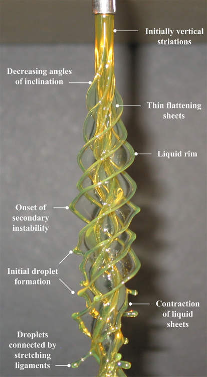
In fluid dynamics, we like to classify flows as laminar–smooth and orderly–or turbulent–chaotic and seemingly random–but rarely is any given flow one or the other. Many flows start out laminar and then transition to turbulence. Often this is due to the introduction of a tiny perturbation which grows due to the flow’s instability and ultimately provokes transition. An instability can typically take more than one form in a given flow, based on the characteristic lengths, velocities, etc. of the flow, and we classify these as instability modes. In the case of the vertical rotating viscous liquid jet shown above, the rotation rate separates one mode (n) from another. As the mode and rotation rate increase, the shape assumed by the rotating liquid becomes more complicated. Within each of these columns, though, we can also observe the transition process. Key features are labeled in the still photograph of the n=4 mode shown below. Initially, the column is smooth and uniform, then small vertical striations appear, developing into sheets that wrap around the jet. But this shape is also unstable and a secondary instability forms on the liquid rim, which causes the formation of droplets that stretch outward on ligaments. Ultimately, these droplets will overcome the surface tension holding them to the jet and the flow will atomize. (Video and photo credits: J. P. Kubitschek and P. D. Weidman)

Using Flow Viz for Optimization


Flow visualization is a powerful design tool for engineers. When Google was interested in determining optimal configurations for their heliostat array, they turned to NASA Ames’ water tunnel facility to test upstream barriers to deflect flow off the heliostats. In each photo, flow is from left to right and fluorescent dye is used to mark streamlines and reveal qualitative flow detail. Upstream of the obstacles, the streamlines are coherent and laminar, but after deflection, the flow breaks down into turbulence. In this case, such turbulence is desirable because it lowers the local fluid velocity and thus the aerodynamic loads experienced by each heliostat, potentially allowing for a savings in fabrication. For more, see Google’s report on the project. (Photo credits: google.org)