Fluorescent oil sprayed onto a model in the NASA Langley 14 by 22-Foot Subsonic Wind Tunnel glows under ultraviolet light. Airflow over the model pulls the initially even coat of oil into patterns dependent on the air’s path. The air accelerates around the curved leading edge of the model, curling up into a strong lifting vortex similar to that seen on a delta wing. At the joint where the wings separate from the body those lifting vortices appear to form strong recirculation zones, as evidenced by the spiral patterns in the oil. Dark patches, like those downstream of the engines could be caused by an uneven application of oil or by areas of turbulent flow, which has larger shear stress at the wall than laminar flow and thus applies more force to move the oil away. Be sure to check out NASA’s page for high-resolution versions of the photo. (Photo credit: NASA Langley/Preston Martin; via PopSci)
Tag: airplanes

Visualizing F-18 Flow
Flow visualization techniques are helpful outside of wind and water tunnels, too. The photo above comes from the F-18 High Alpha Research Vehicle (HARV) program in which techniques like smoke and dye visualization were used in-flight to visualize airflow around an F-18 at large angles of attack. During flight a glycol-based liquid dye was released from tiny holes along the plane’s forebody, creating the pattern seen here later on the ground. This particular test corresponded to about 26 degrees angle of attack. (Photo credit: NASA Dryden)

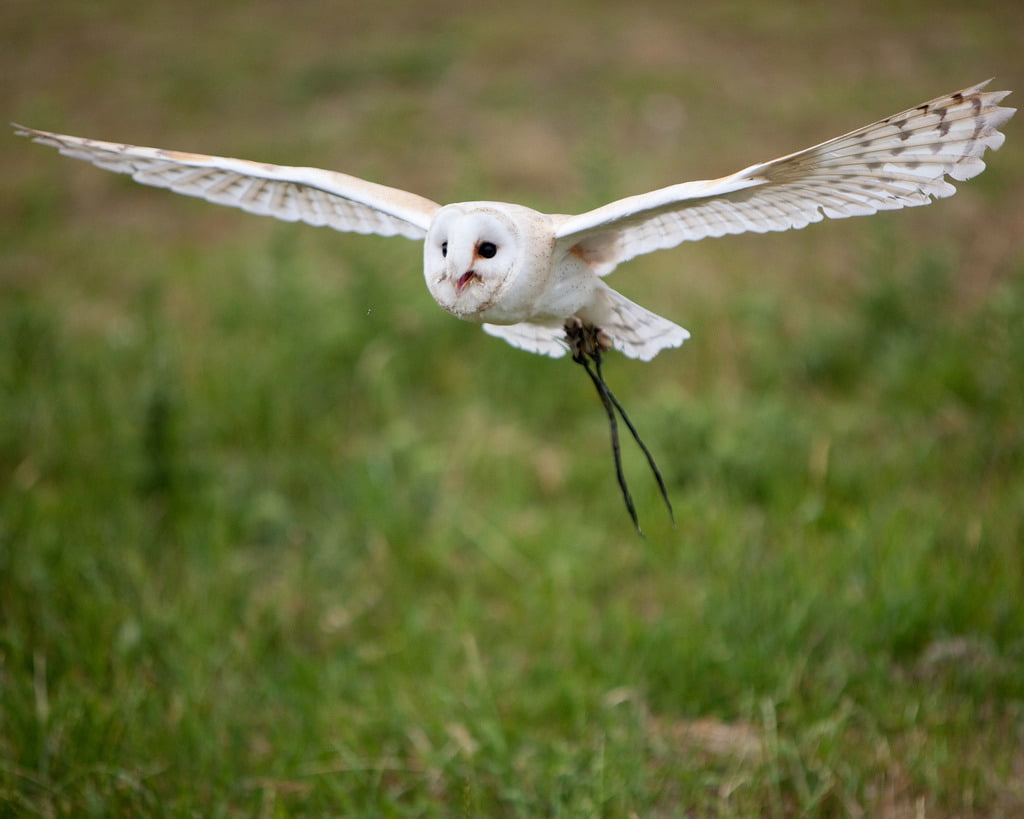
The Silence of Owls
Owls are nearly silent hunters, able to swoop down on their prey without the rush of air over their wings giving away their approach, thanks to several key features of their feathers. The trailing edge of their feathers–or any lifting body, like an airplane wing–are a particular source of acoustic noise due to the interaction of turbulence near the surface with the edge. Since owls are especially good at eliminating self-produced noise in a frequency range that overlaps human hearing, investigators want to learn what works for owls and apply to it aircraft. A recent theoretical analysis uses a simplified model of the feather as a porous, elastic plate. The researchers found that the combination of porosity with the elasticity of the trailing edge significantly reduced noise relative to a rigid edge. (Photo credit: N. Jewell; research credit: J. Jaworski and N. Peake)

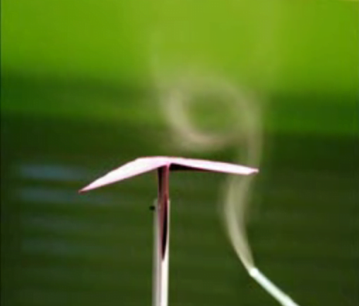
Lift on a Paper Plane
In this still image from a student experiment, smoke visualization shows the formation of a vortex over the wing of a paper airplane during a wind tunnel test. This wing vortex is mirrored on the opposite wing, though there is no smoke to show it. At high angle of attack, the delta-wing shape of the traditional paper air plane creates these vortices on the upper surface, which helps generate the lift necessary to keep the plane aloft. (Photo credit: A. Lindholdt, R. Frausing, C. Rechter, and S. Rytman)

Shock Waves in Flight
Schlieren photography allows visualization of density gradients, such as the sharp ones created by shock waves off this T-38 aircraft flying at Mach 1.1 around 13,000 ft. Although shock waves are relatively weak at this low supersonic Mach number, they persist, as seen in the image, at significant distances from the craft. The sonic boom associated with the passage of such a vehicle overhead is due to the pressure change across a shock wave. The higher the altitude of the supersonic craft, the less intense its shock wave, and thus sonic boom, will be by the time it reaches ground level. (Photo credit: NASA)

Those Funny Fins on Airplane Wings
Ever look out an airplane’s window and wondered why a row of little fins runs along the upper side of the wing? These vortex generators help prevent a wing from stalling at high angle of attack by keeping flow attached to the surface. Airflow over the vanes creates a tip vortex that transports the higher-momentum fluid from the freestream closer to the wing’s surface, increasing the momentum in the boundary layer. As a result of this momentum exchange, the boundary layer remains attached over a greater chordwise distance. This also increases the effectiveness of trailing-edge control surfaces, like ailerons, on the wing. (Photo credit: Mark Jones Jr.)

Unmanned Aerial Vehicles


In recent years unmanned aerial vehicles (UAVs) have grown in popularity for both military and civilian application and are shifting from a remotely controlled platform to autonomous control. Since no pilot flies onboard an UAV, these craft are much smaller than other fixed-wing aircraft, with wingspans that may range from a few meters to only centimeters. At these sizes, most fixed-wing airfoil theory does not apply because no part of the wing is isolated from end effects. This complicates the prediction of lift and drag on the aircraft, particularly during maneuvering and necessitates the development of new predictive methods and control schemes. Shown above are flow visualizations of a small UAV executing a perching maneuver, intended to allow the craft to land as a bird does by scrubbing speed with a high-angle-of-attack, high-drag motion. (Photo credit: Jason Dorfman; via Hizook; requested by mindscrib)

Vapor Cone
This stunning National Geographic photo contest winner shows an F-15 banking at an airshow and a array of great fluid dynamics. A vapor cloud has formed over the wings of the plane due to the acceleration of air over the top of the plane. The acceleration has dropped the local pressure enough that the moisture of the air condenses. Some of this condensation has been caught by the wingtip vortices, highlighting those as well. Finally, the twin exhausts have a wake full of shock diamonds, formed by a series of shock waves and expansion fans that adjust the exhaust’s pressure to match that of the ambient atmosphere. (Photo credit: Darryl Skinner/National Geographic; via In Focus; submitted by jshoer)

Wingtip Vortices
Any finite length wing produces wingtip vortices–potentially intense regions of rotational flow downstream of the wing’s ends. These vortices are associated both with the production of lift on the wing and with unavoidable induced drag. The tabletop demonstration above shows the region of the vortices’ influence and how strong the rotation is there. Note also that the two vortices have opposite rotational senses–the left side induces a clockwise rotation, whereas the right side induces an anti-clockwise rotation. The larger an aircraft, the stronger and longer lasting its vortices; this can be a source of danger for smaller aircraft passing through the wake. If a pilot crosses one wingtip vortex and overreacts to compensate, crossing the second counter-rotating vortex can cause even greater damage.
Stalling a Wing
At small angles of attack, air flows smoothly around an airfoil, providing lifting force through the difference in pressure across the top and bottom of the airfoil. As the angle of attack increases, the lift produced by the airfoil increases as well but only to a point. Increasing the angle of attack also increases the adverse pressure gradient on the latter half of the top surface, visible here as an increasingly thick bright area. Over this part of the surface, the pressure is increasing from low to high–the opposite of the direction a fluid prefers to flow. Eventually, this pressure gradient grows strong enough that the flow separates from the airfoil, creating a recirculating bubble of air along much of the top surface. When this happens, the lift produced by the airfoil drops dramatically; this is known as stall.