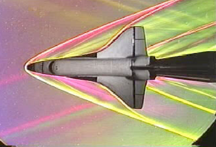
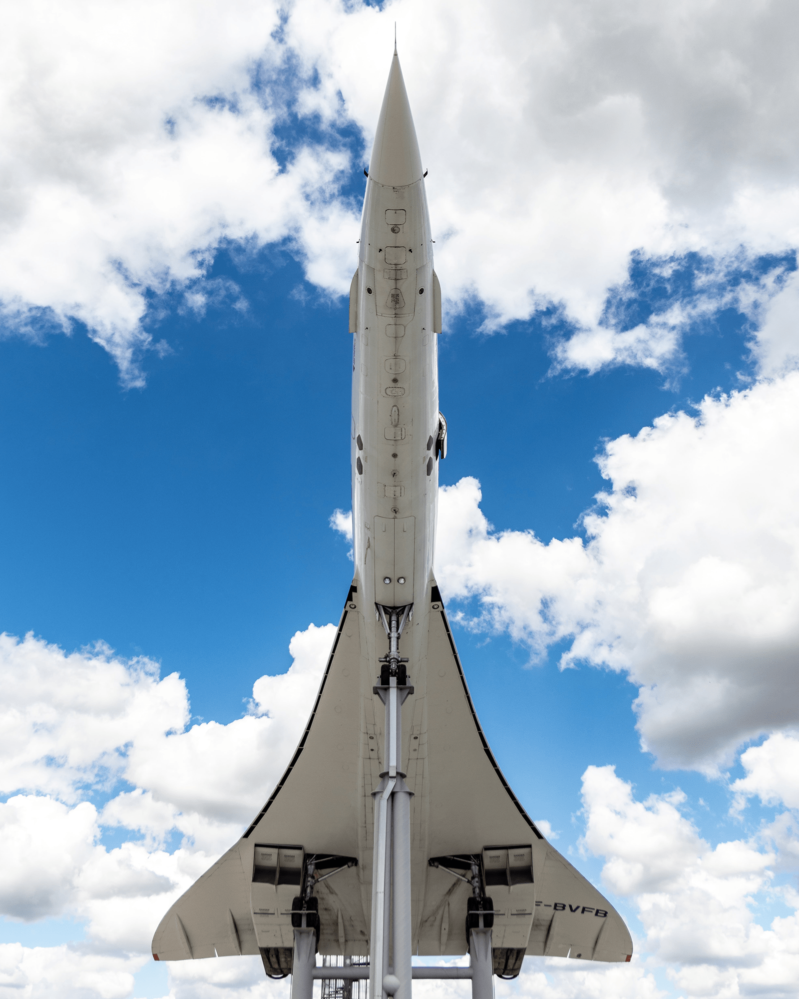
Tag: supersonic

  • Plasma Shock Waves

    Plasma Shock Waves

    Solar flares and coronal mass ejections send out shock waves that reverberate through our solar system. But shock waves through plasma – the ionized, high-energy particles making up the solar wind – do not behave like our typical terrestrial ones. Instead of traveling through collisions between particles, these astrophysical shock waves are driven by interactions between moving, charged particles and magnetic fields. 

    A driving burst of plasma accelerated into ambient plasma creates electromagnetic forces that accelerate ambient ions to supersonic speeds, pushing the shock wave onward even without particles directly colliding. Thus far, piecing together the physics of these interactions has been a challenge because spacecraft are limited in what and where they can measure. But a group here on Earth has now recreated and observed some of this process in the lab. (Image credit: NASA Solar Dynamics Observatory; research credit: D. Schaeffer et al.; via phys.org)

  • Astrophysical Turbulence

    Astrophysical Turbulence

    Subsonic turbulence – like the random and chaotic motions of air and water in our everyday lives – is something we have only a limited understanding of. Our knowledge of supersonic turbulence, where shock waves and compressibility rule, is even more tenuous. In part this is because, although we can observe snapshots of supersonic turbulence in astronomical settings like the Orion Nebula shown above, we cannot watch it evolve. On these scales, features simply don’t change appreciably on human timescales.

    This has limited scientists to mostly numerical and theoretical studies of supersonic turbulence, but that is starting to change. Researchers are now building experimental set-ups that collide laser-driven plasma jets to generate boundary-free turbulence at Mach 6. Thus far, the observations are consistent with what’s been seen in nature: at low speeds, the turbulence is consistent with Kolmogorov’s theories, with energy cascading from large scales to smaller ones predictably. But as the Mach number increases, the nature of the turbulence shifts, moving toward the large density fluctuations seen in nebulae and other astrophysical realms. (Image credit: F. Battistella; research credit: T. White et al.; see also Nature Astronomy; submitted by Kam-Yung Soh)

  • Seeing Shock Waves

    Seeing Shock Waves

    This week NASA released the first-ever image of shock waves interacting between two supersonic aircraft. It’s a stunning effort, requiring a cutting-edge version of a century-old photographic technique and perfect coordination between three airplanes – the two supersonic Air Force T-38s and the NASA B-200 King Air that captured the image. The T-38s are flying in formation, roughly 30 ft apart, and the interaction of their shock waves is distinctly visible. The otherwise straight lines curve sharply near their intersections.

    Fully capturing this kind of behavior in ground-based tests or in computer simulation is incredibly difficult, and engineers will no doubt be studying and comparing every one of these images with those smaller-scale counterparts. NASA developed this system as part of their ongoing project for commercial supersonic technologies. (Image credit: NASA Armstrong; submitted by multiple readers)

  • Noisy Jets

    Noisy Jets

    One major problem that has plagued supersonic aircraft is their noise. The Concorde – thus far the only supersonic commercial airliner – was plagued with noise complaints that ultimately restricted its usability. Noise reduction is a major area of inquiry in aerospace, and the video below shows one experiment trying to understand the connections between supersonic flow and noise.

    Above you see a supersonic, Mach 1.5 microjet emanating from a nozzle at the top of the image. The jet is hitting a flat plate at the bottom of the image. Just beyond nozzle’s exit, you can see the X-shape of shock waves inside the jet. The position of that X is oscillating up and down.

    In the background, you can see horizontal light and dark lines traveling up and down. Those horizontal lines in the background are acoustic waves. When they hit the bottom plate, they reflect and travel upward until they hit another surface (outside the picture) and reflect back down. As they travel, they interact with the jet, causing those X-shaped shock waves to move up and down. This coupling between flow and acoustic waves makes the jet much louder – up to 140 dB – than it would be otherwise.

    Researchers hope that unraveling the physics of simpler systems like this one will help them quiet more complicated aircraft. (Image and video credit: F. Zigunov et al.)

  • Space Shuttle Sonic Booms

    Space Shuttle Sonic Booms

    The Space Shuttle had a famous double sonic boom when passing overhead during re-entry. This schlieren flow visualization of a model shuttle at Mach 3 reveals the source of the sound: the fore and aft shock waves on the vehicle. The nose of the shuttle generates the strongest shock wave since it is the first part of the vehicle the flow interacts with. This initial shock wave turns the flow outward and around the shuttle. The second boom comes from the back of the shuttle and serves to turn the flow back in to fill the wake behind the shuttle. (The actual shock wave would look a little different than this one because there’s no sting holding the shuttle like there is with the model.) The other major shock wave comes from the shuttle’s wings, but, at least for this Mach number, the wing shock wave merges with the bow shock, making the two indistinguishable. (Image credit: G. Settles, source)

  • Rocket Launch Systems

    Rocket Launch Systems

    If you’ve ever watched a rocket launch, you’ve probably noticed the billowing clouds around the launch pad during lift-off. What you’re seeing is not actually the rocket’s exhaust but the result of a launch pad and vehicle protection system known in NASA parlance as the Sound Suppression Water System. Exhaust gases from a rocket typically exit at a pressure higher than the ambient atmosphere, which generates shock waves and lots of turbulent mixing between the exhaust and the air. Put differently, launch ignition is incredibly loud, loud enough to cause structural damage to the launchpad and, via reflection, the vehicle and its contents.

    To mitigate this problem, launch operators use a massive water injection system that pours about 3.5 times as much water as rocket propellant per second. This significantly reduces the noise levels on the launchpad and vehicle and also helps protect the infrastructure from heat damage. The exact physical processes involved – details of the interaction of acoustic noise and turbulence with water droplets – are still murky because this problem is incredibly difficult to study experimentally or in simulation. But, at these high water flow rates, there’s enough water to significantly affect the temperature and size of the rocket’s jet exhaust. Effectively, energy that would have gone into gas motion and acoustic vibration is instead expended on moving and heating water droplets. In the case of the Space Shuttle, this reduced noise levels in the payload bay to 142 dB – about as loud as standing on the deck of an aircraft carrier. (Image credits: NASA, 1, 2; research credit: M. Kandula; original question from Megan H.)

  • Capturing SLS

    Capturing SLS

    NASA’s recent full-scale ground test of their Space Launch System (SLS) rocket was notable for more than just the engine. It was an opportunity to use a new high dynamic range, high speed camera prototype,

    HiDyRS-X, to capture the rocket’s exhaust in detail never seen before. Usually the extreme brightness of the rocket exhaust makes it impossible to see any structure in the flow without completely obscuring the ground equipment. With this camera, however, engineers can see how the engine, exhaust, and surroundings all interact. Be sure to check out the full video. I particularly like watching how the rocket’s exhaust entrains dust and sand from the ground nearby.  (Image credit: NASA, source; submitted by Chris P. and Matt S.)

  • The Bubble Nebula

    The Bubble Nebula

    This spectacular Hubble image shows the Bubble Nebula. The source of this nebula is the star seen toward the upper left side of the bubble. This massive, super-hot star has ceased to fuse hydrogen and is now fusing helium, powering its way to a likely end as a supernova. As it burns, the star emits a stellar wind of gas moving at over 6.4 million kilometers an hour. As the flow moves outward, it encounters colder dense gases that it pushes along as it expands; this is the blue bubble surface that we see. The asymmetry of the bubble with respect to its source star is caused by the variation in the surrounding gas’s density. The bubble’s front moves more slowly in areas with more gas, thus making the bubble appear lop-sided. (Image credit: NASA; via Gizmodo)

  • Shock Waves in Flight

    Shock Waves in Flight

    This week NASA released two new images of the shock waves surrounding T-38C jets in free flight. They’re the result of NASA’s new adaptations of the schlieren photography technique, which has let scientists visualize shock waves (in the lab, at least) for more than a century. To celebrate, I thought it would be fun to demonstrate some of the data engineers can extract from images like the one above. So I’m going to show you how to calculate how fast this plane was flying!

    Shock waves depend a lot on geometry. This is not too surprising, really, since shock waves are nature’s way of quickly turning the air because there’s an object in the way. This leads to a very powerful observation, though: the angle of a shock wave depends on the geometry of the object and the Mach number of the flow. (The Mach number is the ratio of an object’s speed to the local speed of sound, so an object moving at Mach 1 is moving at the speed of sound.)

    The reverse observation is also true: if we can measure the angle of a shock wave from a known geometry, then we can calculate the Mach number. Now, I don’t have any special information about the geometry of a T-38, so most of the shock waves in this picture can’t tell me much quantitatively.

    But, it turns out, I don’t need to know anything about the geometry of the plane to figure out its Mach number. That’s because that very first shock wave over on the right is coming off a sharp probe mounted over the airplane’s nose. The probe is sharp enough, in fact, that I can treat it as though it’s a tiny point disturbance. That means that rightmost shock wave is a special kind of shock known as a Mach wave, and its geometry depends solely on the Mach number. It’s a pretty simple equation, too:

    image

    So, all I have to do is fire up some software like GIMP or ImageJ and estimate the angle of that first shock wave.

    image

    I came up with an estimate of about 77 degrees for the shock wave angle, which gives Mach 1.026 for the plane’s speed. Keep in mind that a) I’m using a grainy photo; and b) I have no information about the plane’s orientation relative to the camera. Nevertheless, NASA’s caption reports that this plane was moving at Mach 1.05 in the picture. My quick and dirty estimate is only off by 2%!

    Of course, engineers are interested in a lot more than estimating an aircraft’s speed from these photos. With a little more geometry information, they can gather a lot of useful data from these images. One of the goals for the new photography technique is to help study new aircraft designs that generate weaker shock waves and quieter sonic booms. (Original images: NASA)

  • Shock Diamonds

    Shock Diamonds

    Rocket engine exhaust often contains a distinctive pattern known as shock diamonds or Mach diamonds. These are a series of shock waves and expansion fans that increase and decrease, respectively, the supersonic exhaust gases’ pressure until it equalizes with atmospheric pressure. The bright glowing spots visible to the naked eye are caused by excess fuel in the exhaust igniting. As awesome as shock diamonds look, they’re actually an indication of inefficiencies in the rocket: first, because the exhaust is over- or underexpanded, and second, because combustion inside the engine is incomplete. Both factors reduce a rocket engine’s efficiency (and both are, to some extent, inescapable). (Photo credit: XCOR)