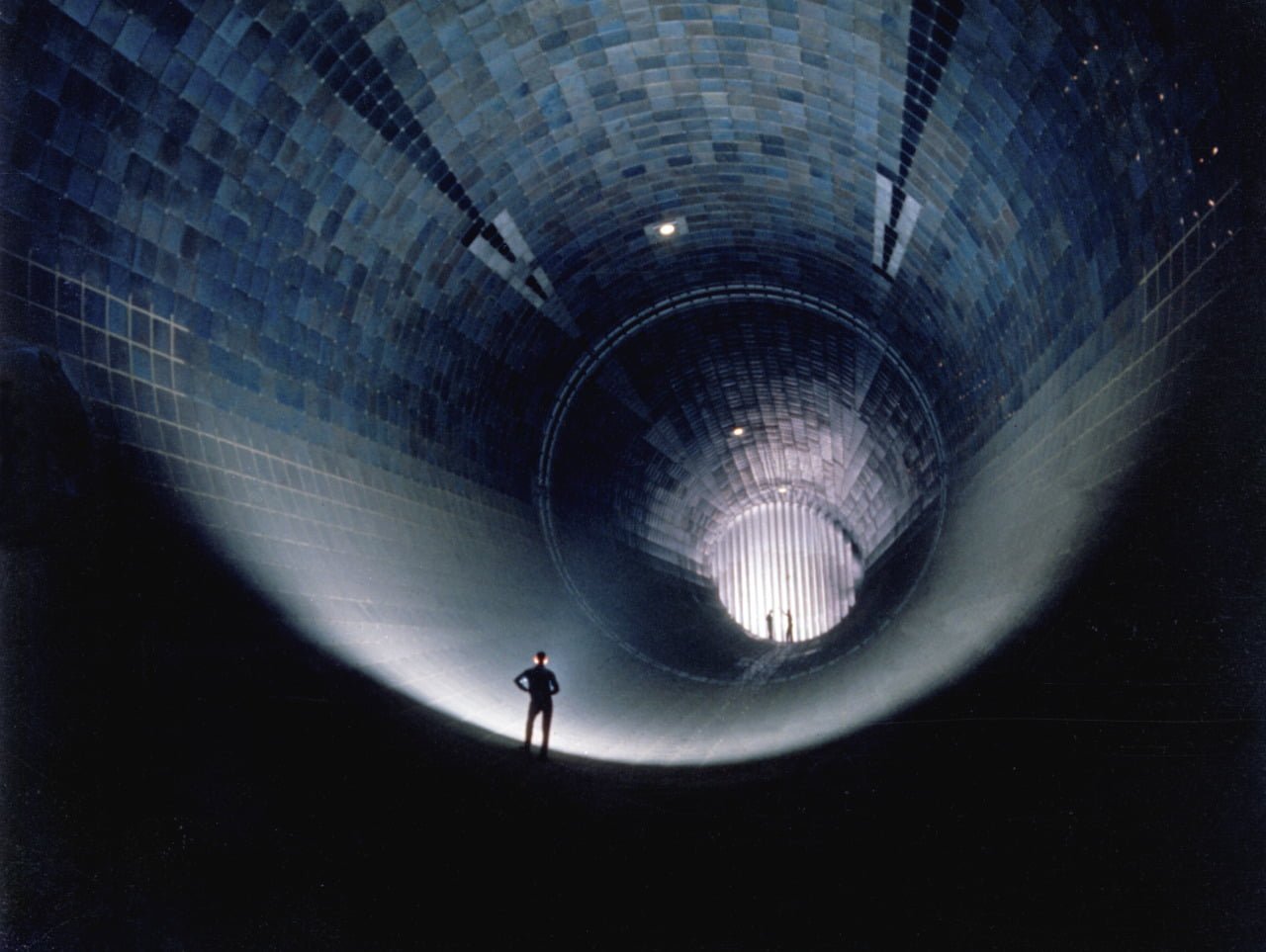
This 1960 photo shows three men standing inside Arnold Engineering Development Complex’s 16-ft supersonic wind tunnel facility. The wind tunnel was capable of Mach numbers between 1.60 and 4.75 through a test section 4.8 meters wide and 20.2 meters long. It served as a large-scale testing facility for aircraft and propulsion systems. Like many large-scale and high-speed wind tunnel facilities in the United States, it is no longer active. In recent years, many unique wind tunnel facilities at NASA, military bases, and universities have been closed down, depriving researchers and engineers of the ability to include large-scale testing in their design and development of new technologies. These facility closures leave a substantial gap between the speeds and Reynolds numbers achievable in small-scale experiments and computational fluid dynamics and those experienced in flight. (Photo credit: P. Tarver)
Tag: supersonic

Protostellar Jets
As young stars form, they often produce narrow high-speed jets from their poles. By astronomical standards, these fountains are dense, narrowly collimated, and quickly changing. The jets have been measured at velocities greater than 200 km/s and Mach numbers as high as 20. The animation above (which you should watch in its full and glorious resolution here) is a numerical simulation of a protostellar jet. Every few decades the source star releases a new pulse, which expands, cools, and becomes unstable as it travels away from the star. Models like these, combined with observations from telescopes like Hubble, help astronomers unravel how and why these jets form. (Image credit: J. Stone and M. Norman)
ETA: As it happens, the APOD today is also about protostellar jets, so check that out for an image of the real thing. Thanks, jshoer!

Controlling Supersonic Flight
The forces on an object in flight come from the distribution of pressure on the surface. To alter an object’s trajectory, one has to shift the pressure distribution. On subsonic and transonic aircraft, this is usually done with control surfaces like an aileron, but at supersonic speeds this can require a lot of force. The schlieren images above show an alternative approach in which a plasma actuator near the nosetip generates asymmetric forces on the cone. The actuator discharges plasma at t=0, and flow is from left to right. In the first image, the bubble of plasma is expanding on the upper side of the cone, disrupting the nearby shock wave. Over time, it moves downstream, carrying its disruption with it. The asymmetric effect of the plasma causes uneven pressures on either side of the cone that can be triggered in order to turn it in flight. (Photo credit: P. Gnemmi and C. Rey)

Bullet Through a Bubble
A bullet passes through a soap bubble in the schlieren photo above. The schlieren optical technique is sensitive to changes in the refractive index and, since a fluid’s refractive index changes with density, permits the visualization of shock waves. A strong curved bow shock is visible in front of the bullet as well as weaker lines marking additional shocks waves around the bullet. Impressively, the bullet’s passage is so fast (and the photo’s timing so perfect) that there are no imperfections or signs of bursting in the soap bubble. The photo’s caption suggests that the bubble may be filled with multiple gases. If they are unmixed and of differing densities, this may be the source of the speckling and plume-like structures inside the bubble. Incidentally, if anyone out there has high-speed schlieren video of a bullet passing through a soap bubble, I would love to see it. (Photo credit: H. Edgerton and K. Vandiver)

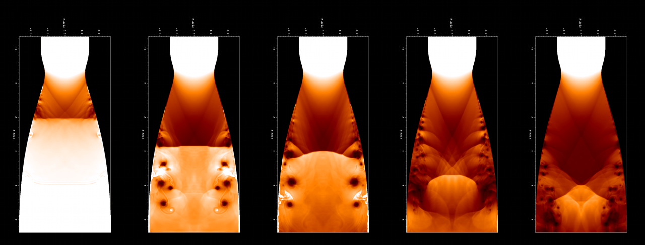
Start Your Rocket Engine
When supersonic flow is achieved through a wind tunnel or rocket nozzle, the flow is said to have “started”. For this to happen, a shock wave must pass through, leaving supersonic flow in its wake. The series of images above show a shock wave passing through an ideal rocket nozzle contour. Flow is from the top to bottom. As the shock wave passes through the nozzle expansion, its interaction with the walls causes flow separation at the wall. This flow separation artificially narrows the rocket nozzle (see images on right), which hampers the acceleration of the air to its designed Mach number. It also causes turbulence and pressure fluctuations that can impact performance. (Image credit: B. Olson et al.)

Shocked Interfaces
The Richtmyer-Meshkov instability occurs when two fluids of differing density are hit by a shock wave. The animation above shows a cylinder of denser gas (white) in still air (black) before being hit with a Mach 1.2 shock wave. The cylinder is quickly accelerated and flattened, with either end spinning up to form the counter-rotating vortices that dominate the instability. As the vortices spin, the fluids along the interface shear against one another, and new, secondary instabilities, like the wave-like Kelvin-Helmholtz instability, form along the edges. The two gases mix quickly. This instability is of especial interest for the application of inertial confinement fusion. During implosion, the shell material surrounding the fuel layer is shock-accelerated; since mixing of the shell and fuel is undesirable, researchers are interested in understanding how to control and prevent the instability. (Image credit: S. Shankar et al.)The APS Division of Fluid Dynamics conference begins this Sunday in Pittsburgh. I’ll be giving a talk about FYFD Sunday evening at 5:37pm in Rm 306/307. I hope to see some of you there!

Schlieren in Flight
Schlieren photography is a common method of visualizing shock waves in wind tunnel experiments, but it’s much harder to pull off for aircraft in the sky. This video from NASA shows off some stunning work out of NASA Dryden capturing schlieren video of shock waves from a F-15B aircraft at Mach 1.38. You’ll notice that shock waves extend off the nose, wings, tail, and other parts of the airplane and extend well beyond the camera’s field of view. It’s these shock waves hitting the ground level that causes distinctive sonic booms. These tests are part of NASA’s on-going research into minimizing the effects of sonic boom so that civilian supersonic flight over land is feasible in the future. When the U.S. government shutdown ends, you’ll be able to learn more about this work at NASA Dryden’s GASPS page. (Video credit: NASA Dryden)

Fluids Round-up – 5 October 2013
This is the last week that my IndieGoGo project is open for donations. All money above and beyond what is needed for the conference will go toward FYFD-produced videos. Also, donors can get some awesome FYFD stickers.
As a reminder, those looking for more fluids–in video, textbook, or other form–can always check out my resources page. And if you know about great links that aren’t on there, let me know so that I can add them. On to the round-up!
- Popular Science has look at what it was like to fly on the Concorde, the only supersonic commercial airliner ever flown.
- For the cyclists and CFD folks out there, Zipp has put out a new video discussing their Firecrest wheels’ aerodynamics.
- io9 explains how superhydrophobic surfaces impart a charge to water droplets and how this can be used to increase efficiency at power plants.
- BuzzFeed UK has 32 fun science GIFs, several of which are fluids-related, and several of which will look familiar to long-time readers. (via Flow Visualization on FB)
- Wired has an intriguing short on Acoustic Archives, a group that focuses on capturing the acoustic qualities of historic locations using custom-designed 3D microphones.
- Congratulations to Richard over at Flow Viz for hitting his 100th post! Here’s to many more.
- Finally, our lead image comes from Martin Klimas. Smithsonian’s blog has a feature on his work in which he transforms songs from artists like Pink Floyd, Daft Punk, and Bach into sonic sculptures using paint on speakers. (via Flow Visualization on FB)
I had a lot of fun earlier this week giving a talk for the Texas A&M Applied Mathematics Undergraduate Seminar series. I didn’t get a chance to record it, but the slides are up here if anyone is interested.(Photo credit: M. Klimas)Shock Trains
In compressible flows, shock waves are singularities, a tiny distance across which the density, temperature, and pressure of a fluid change suddenly and discontinuously. In this video, there is a wedge at the top and bottom of the frame and a Pitot probe roughly in the center. Flow is left to right and is initially subsonic. Once Mach 6 flow is established in the wind tunnel, a series of shock waves and expansion fans appear as light and dark lines in this schlieren video. Oblique shocks extend from the sharp tip of each wedge and interfere to create a normal shock in front of the Pitot probe. The air that passes through the normal shock is subsonic to the right of the shock, whereas air that goes through the oblique shocks remains supersonic. The fainter lines further to the right are weaker shock waves and expansion fans that reflect off the walls and probe. They exist to continue turning the airflow around the probe and to equalize conditions between different regions. (Video credit: C. Mai et al.)
Rocket Sonic Boom
Originally posted: 22 July 2010 This video of the NASA Solar Dynamics Observatory’s launch is such a favorite of mine that it was part of the original inspiration for FYFD and was the very first video I posted. Watch closely as the Atlas V rocket climbs. At 1:51 you’ll see a rainbow-like cloud in upper right corner of the screen. This effect is created by sunlight shining through ice crystals of the cloud. A couple seconds later you see pressure waves from the rocket propagate outward and destroy the rainbow effect by re-aligning the ice crystals. Just after that comes the announcement that the vehicle has gone supersonic. The atmospheric conditions of the launch happened to be just right to make those pressure waves coming off the rocket visible just before they coalesced into a leading shockwave. (Video credit: B. Tomlinson)
Reminder: If you haven’t already, please fill out our reader survey and help us improve FYFD!


