
Archer fish hunt by shooting jets of water at their prey to knock them into the water where the fish can eat them. Previous research showed that the archer fish’s projectile jet is pulsed such that the water released at a later time has a greater velocity. This makes the jet bunch up so that a ball of liquid hits the prey with greater force than the jet would otherwise. A recently released paper shows that the archer fish actively adjust their liquid jets in order to strike targets at different distances while maintaining this bunching effect. To control the jets, the fish adjust both how long they jet and what speed they impart to the fluid by changing how they open and close their mouths. (VIdeo credit: Nature; research credit: P. Gerullis and S. Schuster; via phys.org; submitted by @jchawner)
Tag: physics

Antibubble Vortex Rings
Bubbles are familiar, but antibubbles are a bit more unusual. An antibubble typically has a liquid-air-liquid interface, with a thin shell of air separating a liquid droplet from the surrounding fluid. Although they look rather like bubbles, antibubbles behave differently. Antibubbles are, for example, very sensitive to pressure changes. A sinking antibubble like the one in the video above, experiences a higher pressure on its lower face. This pressure compresses the gas shell and thins it on the bottom. The air shell bursts at the thin point and the antibubble collapses, generating two vortex rings and a small, buoyantly rising bubble. (Video credit: S. Dorbolo et al.)
P.S. – Hello, new followers! Where did you all come from?!

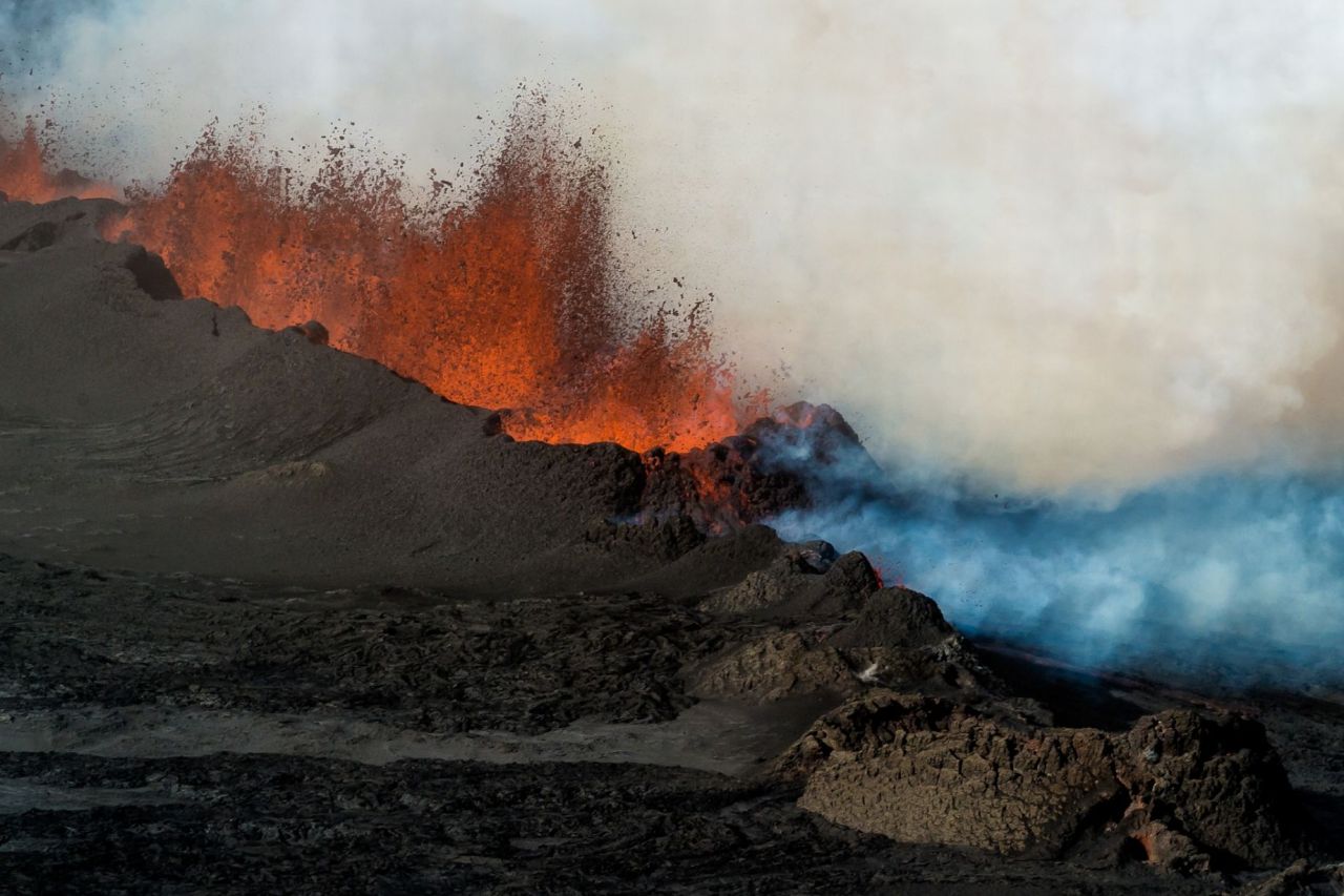
Lava Physics
Lava is rather fascinating as a fluid. Lava flow regimes range from extremely viscous creeping flows all the way to moderately turbulent channel flow. Lava itself also has a widely varying rheology, with its bulk properties like viscosity and its response to deformation changing strongly with temperature and composition. As lava cools, instabilities form in the fluid, causing the folding, coiling, branching, swirling, and fracturing associated with different types and classes of lava. (Image credit: E. Guddman, via Mirror)
The Physics of Sneezing
Sneezing can be a major factor in the spread of some illnesses. Not only does sneezing spew out a cloud of tiny pathogen-bearing droplets, but it also releases a warm, moist jet of air. Flows like this that combine both liquid and gas phases are called multiphase flows, and they can be a challenge to study because of the interactions between the phases. For example, the buoyancy of the air jet helps keep smaller droplets aloft, allowing them to travel further or even get picked up and spread by environmental systems. Researchers hope that studying the fluid dynamics and mathematics of these turbulent multiphase clouds will help predict and control the spread of pathogens. Check out the Bourouiba research group for more. (Video credit: Science Friday)

“Smoke”


Ethereal forms shift and swirl in photographer Thomas Herbich’s series “Smoke”. The cigarette smoke in the images is a buoyant plume. As it rises, the smoke is sheared and shaped by its passage through the ambient air. What begins as a laminar plume is quickly disturbed, rolling up into vortices shaped like the scroll on the end of a violin. The vortices are a precursor to the turbulence that follows, mixing the smoke and ambient air so effectively that the smoke diffuses into invisibility. To see the full series, see Herbich’s website. (Image credits: T. Herbich; via Colossal; submitted by @jchawner, @__pj, and Larry B)
P.S. – FYFD now has a page listing all entries by topic, which should make it easier for everyone to find specific topics of interest. Check it out!

Bioluminescence
In the dark of the ocean, some animals have evolved to use bioluminescence as a defense. In the animation above, an ostracod, one of the tiny crustaceans seen flitting near the top of the tank, has just been swallowed by a cardinal fish. When threatened, the ostracod ejects two chemicals, luciferin and luciferase, which, when combined, emit light. Because the glow would draw undesirable attention to the cardinal fish, it spits out the ostracod and the glowing liquid and flees. Check out the full video clip over at BBC News. Other crustaceans, including several species of shrimp, also spit out bioluminescent fluids defensively. (Image credit: BBC, source video; via @amyleerobinson)

The Churning of Corals


Corals may appear static, but near the surface the tiny hair-like cilia of these polyps are churning the water. Although it has been known for some time that corals have cilia, scientists had previously assumed they only moved water parallel to the coral’s surface. Instead recent flow visualizations show that the cilia’s movements generate larger-scale vortical flows near the coral that can help draw fresh nutrients in as well as flush waste away. This means that, instead of being reliant on currents and tides, corals can exert some control on their environment in order to get what they need. This insight into coral cilia may shed some light on the micro- and macroscopic flows generated by other cilia, like those in our lungs. For a similar example of seemingly-passive organisms generating their own flows, check out how mushrooms create air currents to spread their spores. (Image credits: O. Shapiro et al. and MIT News; source video; h/t to Katie B)
Soap Film Physics
Soap films consist predominantly of water, yet their thin, virtually two-dimensional nature is impossible for water alone to achieve. The small amount of added soap acts as a surfactant, lowering the surface tension of the fluid and preventing it from bursting into droplets. When forming a film, the soap molecules align themselves along the outer surfaces of the film, with their hydrophilic heads among the water molecules and their hydrophobic tails oriented outward. For the most part, the water molecules stay sandwiched between the surfactant layers, forming a film only about as thick as the wavelength of visible light. In fact, the psychedelic colors of a soap film are directly related to the film’s thickness with the black regions being the thinnest. The video above shows a horizontal soap film at the microscopic scale and some of the dynamics exist therein. (Video credit: J. Hart)

ALS Ice Bucket Challenge


When fluid dynamicists get into the ALS ice bucket challenge, they give it a good fluidsy twist. Here are some selections, including lots of high speed video and an infrared video. Check out all those liquid sheets breaking up. Links to the full videos are below. (Image credits: Ewoldt Research Group, source video; TAMU NAL, source video; BYU Splash Lab, source videos 1, 2, 3, 4)

Breaking Drops with Vibration
Atomization is the process of breaking a liquid into a spray of fine droplets. There are many methods to accomplish this, including jet impingement, pressure-driven nozzles, and ultrasonic excitement. In the images above, a drop has been atomized through vibration of the surface on which it rests. Check out the full video. As the amplitude of the surface’s vibration increases, the droplet shifts from rippling capillary waves to ejecting tiny droplets. With the right vibrational forcing, the entire droplet bursts into a fine spray, as seen in the photo above. The process is extremely quick, taking less than 0.4 seconds to atomize a 0.1 ml drop of water. (Photo and video credit: B. Vukasinovic et al.; source video)

