In this video, researcher Leif Ristroph and his colleagues have used a clever way to simulate flapping flight, not by actuating their fliers but by oscillating the flow. The flow is driven by a speaker, which causes the air above it to move up and down. Using straws to simulate the honeycomb flow conditioners often used in wind tunnels helps smooth flow. The end result is a great table-top set-up for testing and refining miniature flier designs. The best fliers stay aloft thanks to asymmetry in the streamwise direction; when the air moves upward, the flier catches the air, maximizing drag so that it is carried upward. When the flow reverses, however, the shape of the flier is more streamlined, so the drag is reduced, helping the flier stay aloft. (Video credit: Science Friday/Leif Ristroph et al.)
Search results for: “wind tunnel”

Fluorescing Shock Waves
Wind tunnel testing plays a major role in the planning of many space missions. Here a model of the Mars Sample Return Orbiter is tested at Mach 10 to determine the heat shield’s response to aerobraking off Mars’ atmosphere. The colors are the result of electron beam fluorescence, in which an electron gun is used to ionize molecules in the flow, which causes them to emit photons (light). The technique can be used for flow visualization–as in the case of the shock waves shown here–or to measure flow characteristics like density, temperature, and velocity. (Photo credit: Thierry Pot/DAFE/ONERA)

Reader Question: How Useful is Flow Viz?
")

")
")
")

Reader Andrew asks:
I’ve noticed you’ve posted a bunch of flow visualization/wind tunnel content. I’m just curious where how useful information is obtained from these. Is it just observation? Or are there instruments that are usually used in conjunction with these techniques to provide data?
Great question, Andrew! The answer can vary based on the technique and application. In some cases, flow visualization is used for purely qualitative observation, but in others it can provide more quantifiable data. For example, the water tunnel flow visualization of Google’s heliostat array gave very qualitative data about flow around a given configuration but allowed quick evaluation of many configurations. Flow visualization can also help identify key features for additional study like vortices in a wake. This identification of structure can be so useful that even in computational fluid dynamics, where researchers have all possible information about pressure, temperature, and velocity in a flow field, flow visualization is regularly used to identify underlying structures.
Some flow visualization methods can also give very specific information. Oil-flow visualization gives a snapshot of shear stress at the surface of an object, letting an engineer identify at a glance areas of laminar and turbulent flow as well as regions with vortices and streaks. Naphthalene flow visualization and infrared thermography are both great for identifying the location of laminar-turbulent transition and can do so across the span of an object, which is much easier than trying to traverse a probe across the entire object. And some forms of flow visualization allow for extraction of velocity field information, as in particle image velocimetry. In this technique, tiny particles seed the flow and carefully timed image pairs are taken and correlated to determine the flow field velocity based on the changes in particle positions between images.
Like every measurement, flow visualization methods have their strengths and limitations. But for many applications, flow visualization provides much more than just pretty pictures and thus remains an important tool in any fluid dynamicist’s arsenal!
Formula 1 Aerodynamics
[original media no longer available]
Computational fluid dynamics (CFD) and the advent of supercomputing have forever changed the way engineers design. Here the use of CFD in the design of Formula 1 racing cars is discussed. Although CFD is used by many companies in place of wind tunnel testing, each method has its advantages. CFD provides information about all flow quantities at all points in the flow but can only do so with an accuracy dependent on the grid and models used. It remains impossible to solve the equations of motion exactly for any problem of practical application because the computational cost is simply too high; instead software packages like FLUENT utilize turbulence models that approximate the physics. Wind tunnel testing, on the other hand, is physically accurate but typically yields only limited data and flow quantities due to the difficulty of instrumentation. (Video credit: BBC News; submitted by carhogg)
(Source: /)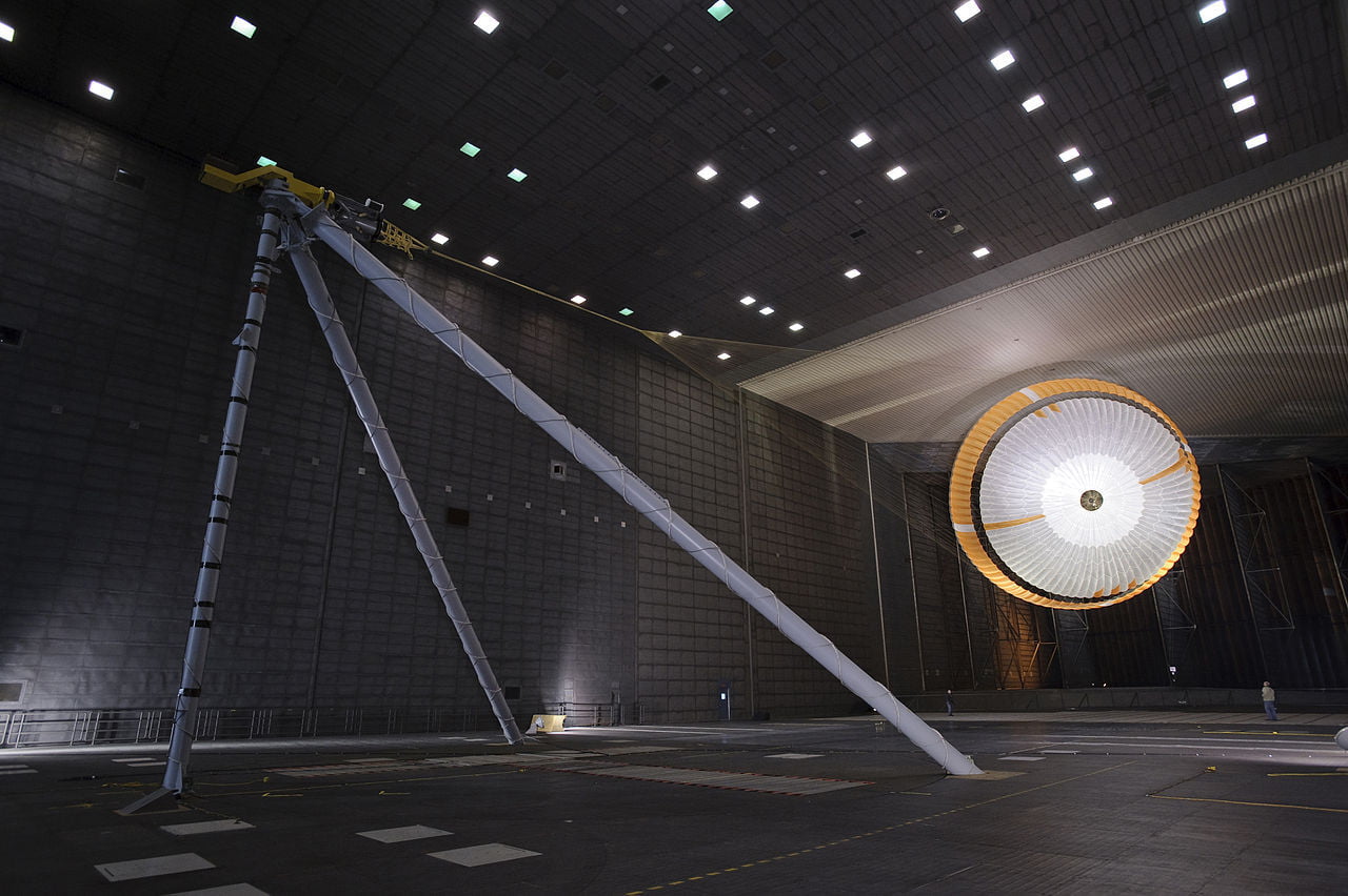
Martian Landing Physics


A little over a week ago, NASA’s Curiosity rover landed on Mars, the culmination of years of engineering. The mission’s landing, in particular, was the subject of intense scrutiny as Curiosity’s size necessitated some new techniques in the final segments of the landing sequence. As it hit the Martian atmosphere at 13,000 mph, the compression of the carbon dioxide behind the capsule’s shock wave slowed the descent. At roughly 1,000 mph–speeds still large enough to be supersonic–Curiosity deployed its parachute. Shown above are the parachute in numerical simulation (from Karagiozis et al. 2011), wind tunnel testing at NASA Ames, and during descent thanks to the Mars Reconnaissance Orbiter. The simulation shows contours of streamwise velocity at different configurations; note the bow shock off the capsule and the additional shocks off the parachute. These help generate the drag needed to slow the capsule. For an interesting behind-the-scenes look at the wind tunnel testing for Curiosity’s parachute check out JPL’s four–part video series. Congratulations to all the scientists and engineers who’ve made the rover a success. We look forward to your discoveries! (Photo credits: K. Karagiozis et al., NASA JPL, NASA MRO)
The Olympic Torch
[original media no longer available]
Today marks the beginning of the 2012 Olympic Games in London. In the opening ceremony, the Olympic flame will complete its journey from Olympia to London, having been carried by some 8,000 torch bearers. Modern Olympic torches are expected to withstand wind, rain, snow, and human error to keep the flame alive and are specially designed and tested for these conditions. Each individual torch is fueled by a mixture of propane and butane stored as a pressurized liquid. The liquid fuel travels through a series of evaporation coils around the burner before combustion. Each torch carries sufficient fuel to burn about fourteen minutes. In addition to computer simulation, the 2012 Olympic torch design was tested in BMW’s Environmental Wind Tunnel to ensure a visible, stable flame for orientations within 45 degrees of vertical in conditions ranging from -5 degrees to 40 degrees Celsius, rain, snow, 35 mph winds, and 50 mph wind gusts. For more on the current torch and previous designs, see How Stuff Works, E&T, and the BBC.
FYFD is celebrating the Olympics by featuring the role of fluid dynamics in sports starting Monday. If you have any burning questions, feel free to ask or email!

Supersonic Flow
This video shows a sphere in a small supersonic wind tunnel at Mach 2.7. Once the tunnel starts, a curved bow shock forms in front of the sphere, close to but not touching the model’s surface. Areas of low pressure are visible behind the sphere, as is a weak shock wave caused by overexpansion in those low pressure areas. Contrast this with a sharp cone in the same tunnel at the same Mach number. In the case of the cone, the shock wave is attached at the nose of the model. The attached shock follows the body more closely, resulting in a shock that impacts the walls of the tunnel further downstream than in the sphere’s case.
Examples of Flutter
Aeroelasticity is the study of the interaction of structural and aerodynamic forces on an object, and its most famous example is flutter, which occurs when the aerodynamic forces on an object couple with its natural structural frequencies in such a way that a violent self-excited oscillation builds. What does that mean? Take a look at the video above. This compilation shows examples of flutter on wind tunnel models, road signs, airplanes, and the Tacoma Narrows Bridge–one of the most famous examples of all time. When air moves over and around an object, like a stop sign, it exerts forces that cause the structure to twist or vibrate. Those vibrations then alter the airflow around the object, which changes the aerodynamic forces on the object. If the motion of the object increases the aerodynamic forces which then increase the oscillation, then a potentially destructive flutter cycle has been created. Flutter is very difficult to simulate computationally, so tests are usually performed experimentally to ensure that any vibrations in the system will damp out rather than grow to the point of structural failure like many of the examples in the film.
Reader Question: How to Get Started in Fluid Dynamics
unboundid-deactivated20131116 asks:
Hi. I’m a freshman engineering student at UCSD, and I was hoping to get more into fluid dynamics. Could you possibly give a quick shake-down of what I should look into if I’m just kind of starting? I want to either work in studying specifically fluid dynamics or in studying interactions of oil and petroleum.
Glad to hear that you’re interested in fluid mechanics! I usually answer these kind of questions privately, but I’m going to go ahead and publish my answer here because I think the advice is useful for any undergraduates interested in fluids.
First of all, most engineering courses of study won’t cover fluid mechanics–outside of pipe flow–until the junior or senior-level courses. This is because, unlike many other engineering topics, fluid mechanics relies heavily on foundational material in other subjects. Although fluid mechanics is still essentially F = ma, writing and manipulating the fundamental equations requires advanced calculus. So you will definitely benefit from paying a lot of attention in your math courses, especially vector calculus and differential equations. I also highly recommend learning to solve differential equations numerically using tools like Matlab or Mathematica. These are super useful skills for just about any form of engineering, but they can really pay off in fluid mechanics.
Now, while this classroom work is very important, you don’t have to wait until you’ve finished four semesters of calculus and physics before getting into fluid mechanics. Look up the professors at your school and the research they do. Find some topics/projects you want to learn more about, and go meet with those professors. In my experience, professors are willing to have undergraduates–yes, even freshmen–volunteer in their labs. I can’t guarantee that you’ll get paid, but I can tell you that you will learn a lot, especially from the graduate students you will probably be assisting. As you gain experience, you’ll gain responsibility. Right now, my research group has a sophomore preparing to be the lead on a new data collection campaign in one of our best research wind tunnels.
Many professors recruit their future graduate students this way. And, if it turns out that you don’t want to work in that lab through graduate school, you will still have a leg up getting into grad school because you’ll have significant research experience and a professor who can write you a strong recommendation, having seen your work. You could even have co-authorship on a publication, and that sort of achievement is going to look good on your resume, whether you pursue graduate school or an industrial job.
In short: talk to professors about their research and find a lab where you can become a part of that research. The earlier you do this, the more impressive the results by the time you graduate. Good luck!

Flow Around a Delta Wing
Smoke visualization in a wind tunnel shows the vortices wrapping around and trailing behind a delta wing. As with more commonly seen rectangular or swept wings, the vortices that form around delta wings affect lift, drag, and control of an aircraft. They can also be hazardous to aircraft nearby. Note that, although delta wings are often seen on supersonic aircraft, this visualization only applies at subsonic speeds. The flow field changes drastically above the speed of sound.