Vertical wind tunnels like this one simulate the experience of skydiving with air speeds up to 270 km/h (168 mph). Here expert freefallers perform a routine similar to synchronized skydiving. By changing the angle and shape of their body with respect to the air flow, they are able to control their lift and drag to produce complex motion in three dimensions.
Search results for: “wind tunnel”
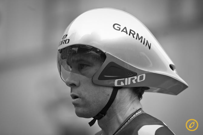
Tour de France Physics: Time Trials
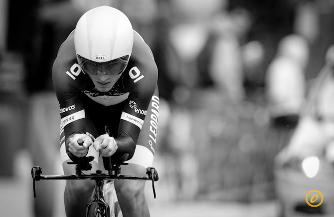
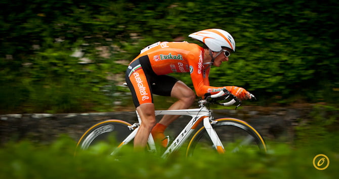
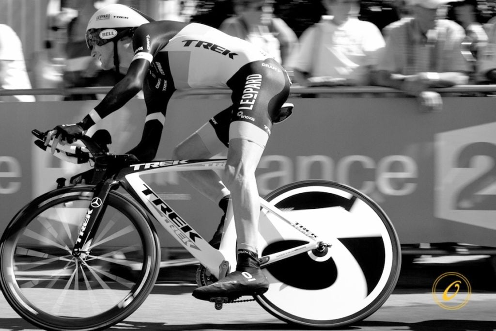
Unlike road stages in which cyclists can draft off one another to reduce drag, in the time trial a cyclist is on a solo race against the clock with nowhere to hide. As a result, the event features lots of technologies designed to reduce both pressure drag and skin friction on the cyclist. For time trials, cyclists wear skinsuits and shoe covers to eliminate any sources of flapping fabrics and to reduce skin friction. They ride bicycles designed to be as light and aerodynamic as possible. Instead of rounded tubing in the frames, these bikes consist of elongated airfoil profiles that direct air past and prevent separation that may increase pressure drag. The rims of their tires are wider and the back wheel is replaced with a disc wheel that allows no airflow aross the wheel. Like the airfoil tubing, these changes help prevent separation. Similarly, riders wear elongated helmets designed to be as aerodynamic as possible while the rider is in the “aero” position, with arms directed out over the wheels, head level, elbows tucked, and back flat. In wind tunnel tests, the rider best able to hold this position will experience the least drag. Even the addition or subtraction of a water bottle is not left to chance, with many time trial bikes designed to be more aerodynamic with a water bottle onboard (though you probably won’t catch the cyclists breaking their aero position to get a drink)! (Photos by Veeral Patel)
FYFD is celebrating the Tour de France with a weeklong exploration of the fluid dynamics of cycling. See previous posts on drafting in the peloton, and pacelining and echelons, and the art of the lead-out train.

X-51A Scramjet Test Flight
The X-51A Waverider hypersonic aircraft had its second test flight earlier this week. Unfortunately, its supersonic combustion ramjet (scramjet) engine failed to transition from its start-up fuel to its primary fuel. According to the US Air Force Research Laboratory:
A US Air Force B-52H Stratofortress released the experimental vehicle from an altitude of approximately 50,000 feet. After release the X-51A was initially accelerated by a solid rocket booster to a speed just over Mach 5. The experimental aircraft’s air breathing scramjet engine lit on ethylene and attempted to transition to JP7 fuel operation when the vehicle experienced an inlet un-start. The hypersonic vehicle attempted to restart and oriented itself to optimize engine start conditions, but was unsuccessful. The vehicle continued in a controlled flight orientation until it flew into the ocean within the test range. #
Un-starting is the term used when supersonic flow is lost in an engine or wind tunnel. If the pressure or temperature in the engine deviates too far from the ideal conditions, the upstream mass flow through the engine will be greater than the downstream mass flow and the engine will choke (video). A shock wave forms and travels upstream, leaving subsonic flow in its wake. Loss of supersonic flow inside the engine would likely also result in losing ignition of the fuel/air mixture, resulting in flameout. #
If you haven’t guessed already, engineers like to make up words.

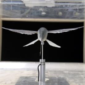
Flow Viz of a Locust
Smoke visualization in a wind tunnel reveals the airflow over a flying locust. Researchers are unraveling the aerodynamics of insect flight in order to produce better Micro Air Vehicles (MAVs) and miniature flying robots. #

Starting a Rocket
This computational fluid dynamics (CFD) simulation shows the start-up of a two-dimensional, ideal rocket nozzle. Starting a rocket engine or supersonic wind tunnel is more complicated than its subsonic counterpart because it’s necessary for a shockwave to pass completely through the engine (or tunnel), leaving supersonic flow in its wake. Here the situation is further complicated by turbulent boundary layers along the nozzle walls. (Video credit: B. Olson)

Pterosaur Aerodynamics
The pterosaur was an enormous prehistoric reptile that flew with wings of living membrane stretched over a single long bone, unlike any of today’s flying creatures. New research using carbon fiber wing analogues and wind tunnel testing suggests that the pterosaur would have been a slow, soaring flyer well adapted to using thermals for lift. Once on a thermal, the pterosaur could coast, perhaps for hours at a time, with little to no flapping necessary. See the research paper or the Scientific American article for more. #
Seeing Shock Waves with Schlieren
Schlieren photography is actually a pretty commonly used system in high-speed experimental aerodynamics. A typical schlieren system will shine a collimated light source on the target (a wind tunnel test section or, above, a candle), bounce that light off a mirror, block half the light with a knife-edge at the focal point, and then record the subsequent images with a camera (high-speed or otherwise). The density of air is closely related to its index of refraction, so light that hits air of a different density will be bent more or less than a neighboring ray. This uneven bending of the light rays due to density gradients is what causes the light and dark areas on the schlieren images. Since the density of air changes drastically across a shock wave, the schlieren system is perfect for visualizing shock waves and has, in fact, been used for that purpose since 1864!
Flying Fish Aerodynamics
New research using wind tunnel measurements of (dead) flying fish is giving new insight into how these fish are able to fly over the waves. Lift and drag data indicates that flying fish have a gliding ability comparable to soaring birds like hawks! #
How Wings Create Lift
One of the topics in fluid dynamics almost everyone has come across is the explanation of how airplanes produce lift. Using Bernoulli’s principle–which relates velocity and pressure–and a picture of an airfoil, your average science text will say that a bit of air going over the top of the airfoil has to travel farther than a bit of air going under the airfoil, and that, therefore, the air over the top travels faster than the air under the airfoil.
Unfortunately, this is misleading and, depending on the wording, outright wrong! The hidden assumption in this explanation is that air that goes over the top and air that goes under the bottom have to reach the trailing edge of the airfoil at the same time. But why would that be? (As one of my profs once said, “There is nothing in physics that says there is Conservation-Of-Who-You-Were-Sitting-Next-To-When-You-Started.”)
Take a look at the video above. It shows an airfoil in a wind tunnel using smoke visualization to show how the air moves. Around the 0:25 mark, the video slows to show a pulse of smoke traveling over the airfoil. What happens at the trailing edge? The smoke going over the top of the airfoil is well past the trailing edge by the time the smoke going under the airfoil reaches the trailing edge!
It’s true that air goes faster over the top of the airfoil than the bottom and that this causes a lower pressure on top of the airfoil (as Bernoulli tells us it should) and that this causes an upward force on the airfoil. But which causes which is something of a chicken-and-egg problem.
A more straightforward way, in my opinion, of explaining lift on an airplane is by thinking about Newton’s 3rd law: for every action, there is an equal and opposite reaction. Take a look at the air’s movement around the airfoil as the angle of attack is increased around 1:00 on the video. Just in front of the airfoil, the air is moving upward. Just after the airfoil, the air is pointed downward. A force from the airfoil has pushed the air down and changed its direction. By Newton’s 3rd law, this means that the air has pushed the airfoil up by the same amount. Voila! Lift!
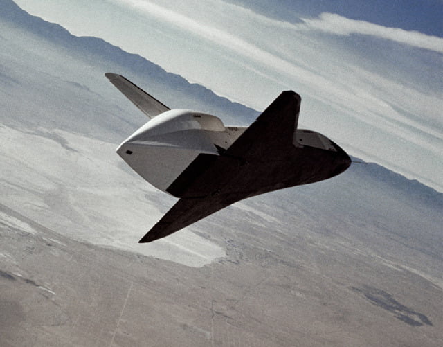
Happy Anniversary, Enterprise!
Wind tunnels are great, but there’s nothing like a flight test to learn about the aerodynamics of a new vehicle. Today in 1977, the space shuttle prototype Enterprise flew on its own for the first time. Enterprise was built purely to test the shuttle’s aerodynamic behavior during gliding and landing. Check out this video of one of Enterprise’s gliding and landing tests.