Category: Research

  • Peering Between Particles

    Peering Between Particles

    Turbulence is not the only way to mix fluids. Even a steady, laminar flow can be an effective mixer if geometry lends a hand. Above, two dyes, fluorescein (green) and rhodamine (red), are injected into a porous flow through packed spheres. The flow runs from bottom to top in both images. Seeing the flow in such a crowded geometry is challenging. Here researchers used spheres with an index of refraction that matches water – that helps them avoid refraction that would prevent them from looking through spheres to the flow on the other side. They also lit a narrow plane of the flow using a laser sheet to isolate it. Together, this allowed the researchers to track the mixing of the two initially separate streaks of dye as they randomly mix in the spaces between spheres. (Image and research credit: M. Kree and E. Villermaux)

  • Forming Craters

    Forming Craters

    Asteroid impacts are a major force in shaping planetary bodies over the course of their geological history. As such, they receive a great deal of attention and study, often in the form of simulations like the one above. This simulation shows an impact in the Orientale basin of the moon, and if it looks somewhat fluid-like, there’s good reason for that. Impacts like these carry enormous energy, about 97% of which is dissipated as heat. That means temperatures in impact zones can reach 2000 degrees Celsius. The rest of the energy goes into deforming the impacted material. In simulations, those materials – be they rock or exotic ices – are usually modeled as Bingham fluids, a type of non-Newtonian fluid that only deforms after a certain amount of force is applied. An everyday example of such a fluid is toothpaste, which won’t extrude from its tube until you squeeze it.

    The fluid dynamical similarities run more than skin-deep, though. For decades, researchers looked for ways to connect asteroid impacts with smaller scale ones, like solid impacts on granular materials or liquid-on-liquid impacts. Recently, though, a group found that liquid-on-granular impacts scale exactly the way that asteroid impacts do. Even the morphology of the craters mirror one another. The reason this works has to do with that energy dissipation mentioned above. As with asteroid impacts, most of the energy from a liquid drop impacting a granular material goes into something other than deforming the crater region. Instead of heat, the mechanism for dissipation here is the drop’s deformation. The results, however, are strikingly alike.  

    For more on how asteroid impacts affect the moon and other bodies, check out Emily Lakdawalla’s write-up, which also includes lots of amazing sketches by James Tuttle Keane, who illustrates the talks he hears at conferences! (Image credits: J. Keane and B. Johnson; via the Planetary Society; additional research and video credit: R. Zhao et al., source; submitted by jpshoer)


  • Lighting Engines

    Lighting Engines

    Combustion is complicated. You’ve ideally got turbulent flow, acoustic waves, and chemistry all happening at once. With so much going on, it’s a challenge to sort out the physics that makes one ignition attempt work while another fails. The animations here show a numerical simulation of combustion in a turbulent mixing layer. The grayscale indicates density contours of a hydrogen-air mixture. The top layer is moving left to right, and the lower layer moves right to left. This sets up some very turbulent mixing, visible in middle as multi-scale eddies turning over on one another.

    Ignition starts near the center in each simulation, sending out a blast wave due to the sudden energy release. Flames are shown in yellow and red. As the flow catches fire, more blast waves appear and reflect. But while the combustion is sustained in the upper simulation, the flame is extinguished by turbulence in the lower one. This illustrates another challenge engineers face: turbulence is necessary to mix the fuel and oxidizer, but turbulence in the wrong place at the wrong time can put out an engine. (Image, research, and submission credit: J. Capecelatro, sources 1, 2)

    image
  • Moving Fluids in the Right Direction

    Moving Fluids in the Right Direction

    One challenge in creating miniature labs-on-a-chip is keeping fluids moving in the desired direction. The top image above shows red and blue droplets being moved toward one another on the top and bottom of a vibrating surface. Eventually, they meet and mix in the middle. To force the fluids in the right direction, the surface is highly textured, as seen in the lower image. These tiny posts and arcs help trap air between the surface and the drop. This makes the drop’s contact area with the superhydrophobic substrate quite small. The arcs provide directionality, and, as the surface shakes, the drops inch along, releasing the arc on the trailing edge as they make contact with a new one. In effect, the droplets walk themselves just where their designers want them to go. (Image and research credit: T. Duncombe et al.; via SciTechDaily)

  • Rheoscopic Flow Vis

    Rheoscopic Flow Vis

    One of the great challenges in visualizing fluid flows is the freedom of movement. A fluid particle – meaning some tiny little bit of fluid we want to follow – is generally free to move in any direction and even change its shape (but not mass). This makes tracking all of those changes difficult, and it’s part of why there are so many different techniques for flow visualization. The technique an experimenter uses depends on the information they hope to get.

    Often a researcher may want to know about fluid velocity in two or more directions, which can require multiple camera angles and more than one laser sheet illuminating the flow. An alternative to such a set-up is shown above. The injected fluid – known as a rheoscopic fluid – contains microscopic reflective particles, in this case mica, that are asymmetric in shape. Imagine a tiny rod, for example. By illuminating the rod from different directions with different colors of light, you can determine the particle’s orientation based on the color it reflects. Since the orientation of the particle depends on the surrounding flow, you can infer how the flow moves. (Image credit and submission: J. C. Straccia; research link: V. Bezuglyy et al.)

  • The Mist of Champagne

    The Mist of Champagne

    If you’ve ever popped open a chilled bottle of champagne, you’ve probably witnessed the gray-white cloud of mist that forms as the cork flies. Opening the bottle releases a spurt of high-pressure carbon dioxide gas, although that’s not what you see in the cloud. The cloud consists of water droplets from the ambient air, driven to condense by a sudden drop in temperature caused by the expansion of the escaping carbon dioxide. Scientifically speaking, this is known as adiabatic expansion; when a gas expands in volume, it drops in temperature. This is why cans of compressed air feel cold after you’ve released a few bursts of air.

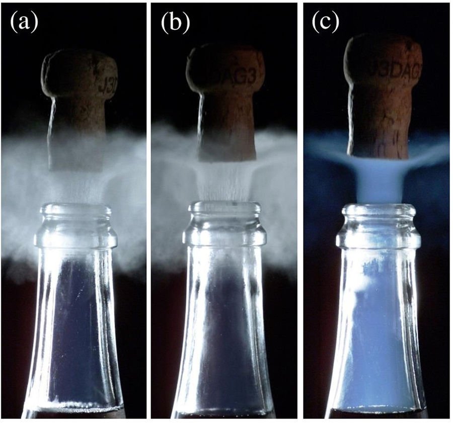
    If your champagne bottle is cold (a) or cool (b), the gray-white water droplet cloud is what you see. But if your champagne is near room temperature ( c ), something very different happens: a blue fog forms inside the bottle and shoots out behind the cork. To understand why, we have to consider what’s going on in the bottle before and after the cork pops.

    A room temperature bottle of champagne is at substantially higher pressure than one that’s chilled. That means that opening the bottle makes the gas inside undergo a bigger drop in pressure, which, in turn, means stronger adiabatic expansion. Counterintuitively, the gas escaping the warm champagne actually gets colder than the gas escaping the chilled champagne because there’s a bigger pressure drop driving it. That whoosh of carbon dioxide is cold enough, in fact, for some of the gas to freeze in that rushed escape. The blue fog is the result of tiny dry ice crystals scattering light inside the bottleneck.

    That flash of blue is only momentary, though, and the extra drop in temperature won’t cool your champagne at all. Liquids retain heat better than gases do. For more, on champagne physics check out these previous posts. (Image and research credit: G. Liger-Belair et al.; submitted by David H.)

  • Building Liquid Circuits

    Building Liquid Circuits

    Building microfluidic circuits is generally a multi-day process, requiring a clean room and specialized manufacturing equipment. A new study suggests a quicker alternative using fluid walls to define the circuit instead of solid ones. The authors refer to their technique as “Freestyle Fluidics”. As seen above, the shape of the circuit is printed in the operating fluid, then covered by a layer of immiscible, transparent fluid. This outer layer help prevent evaporation. Underneath, the circuit holds its shape due to interfacial forces pinning it in place. Those same forces can be used to passively drive flow in the circuit, as shown in the lower animation, where fluid is pumped from one droplet to the other by pressure differences due to curvature. Changing the width of connecting channels can also direct flow in the circuits. This technique offers better biocompatibility than conventional microfluidic circuits, and the authors hope that this, along with simplified manufacturing, will help the technique spread. (Image and research credit: E. Walsh et al., source)

  • Porous Fingers

    Porous Fingers

    If you inject a less viscous fluid, like air, into a narrow gap between two glass plates filled with a more viscous fluid, you’ll get a finger-like instability known as the Saffman-Taylor instability. If you invert the situation – injecting something viscous like water into air – the water will simply expand radially; you’ll get no fingers. But that situation doesn’t hold if there are wettable particles in the air-filled gap. Inject water into a particle-strewn air gap and you get a pattern like the one above. In this case, as the water expands, it collects particles on the meniscus between it and the air. Once the concentration of particles on the meniscus is too high for more particles to fit there, the flow starts to branch into fingers. This creates a greater surface area for interface so that more particles can get swept up as the water expands. (Image and research credit: I. Bihi et al., source)

  • The Rose-Window Instability

    The Rose-Window Instability

    This polygonal pattern is known as the rose-window instability. It’s formed between two electrodes – one a needle-like point, the other flat – separated by a layer of oil. The pointed electrode’s voltage ionizes the air nearby, creating a stream of ions that travel toward the flat electrode below. Oil is a poor conductor, however, so the ions build up on its surface until they’re concentrated enough to form a dimple that lets them reach the lower electrode. At higher voltages, the electrical forces driving the ions and the gravitational force trying to flatten the oil reach a balance in the form of the polygonal cell pattern seen above. Smaller cells form near the needle electrode, where the electrical field is strongest and the temperature is highest, as revealed in thermal and schlieren imaging (lower images) that shows a warm stream of gas impacting there. 

    As a final note, I’ll add that the latest in this research comes from a paper by a Pakastani teenager. It’s never too early to start contributing to research! (Image and research credit: M. Niazi; via NYTimes; submitted by Kam-Yung Soh)

  • Surfing Mists

    Surfing Mists

    Watch your hot cup of coffee or tea carefully, and you may notice a white mist of tiny micron-sized droplets hovering near the surface. These microdroplets are a little understood part of evaporation. They form over a heated liquid, levitating on vapor that diffuses out from them and reflects off the liquid surface. (This is similar to the Leidenfrost effect, but the authors note it occurs at much lower temperatures. Unrelated research has suggested the Leidenfrost effect can occur at lower temperatures when there is very little surface roughness.)

    One of the particularly peculiar behaviors of these tiny levitating microdroplets is that they can exist over dry surfaces as well. The image above shows microdroplets migrating from a liquid surface (right) to a dry surface (center and left). When the droplets near the contact line, they encounter a strong upward flow due to increased evaporation there. This launches the droplets upward and they sail to the dry area. There, their vapor layers continue creating levitation and provide a cushion between them and their neighbors, causing the drops to self-organize into arrays. (Image credit: D. Zaitsev et al.; via Physics World; submitted by Kam-Yung Soh)