Hospital-acquired infections are a serious health problem. One potential source of contamination is through the spread of pathogen-bearing droplets emanating from toilet flushes. The video above includes high-speed flow visualization of the large and small droplets that get atomized during the flush of a standard hospital toilet. Both are problematic for the spread of pathogens; the large droplets settle quickly and contaminate nearby surfaces, but the small droplets can remain suspended in the air for an hour or more. Even more distressing is the finding that conventional cleaning products lower surface tension within the toilet, aggravating the problem by allowing even more small droplets to escape. To learn more, see the Bourouiba research group’s website. (Video credit: Bourouiba research group)
Month: November 2013

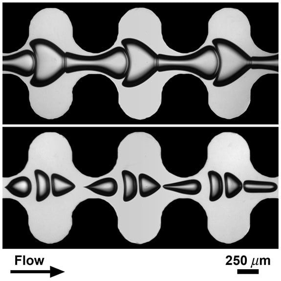
Bubbles Through Constrictions
Surface tension usually constrains bubbles to the smallest area for a given volume – a sphere – but sometimes other forces generate more complicated geometries. The images above show bubbles flowing through microfluidic channels filled with a highly viscous carrier fluid. The bubble size and packing affects the shapes they assume, but so does the geometry of the channel. The narrow constrictions accelerate the flow, elongating the bubbles, whereas the wider channel regions slow the carrier fluid and squish the bubbles together. (Image credit: M. Sauzade and T. Cubaud (Stony Brook University))

Pathlines vs. Streaklines
When considering fluid motion, there are many ways to describe trajectories through the flow. One is the pathline, the trajectory followed by an individual fluid particle. Imagine releasing a rubber duck down a stream. Following the duck’s position over time would give you a pathline. Now imagine that instead of releasing a single rubber duck you release lots of them – say one every half-second from the exact same starting spot. You would end up with a line of rubber ducks stretching downstream, each of them sharing the same origin but with a different starting time. This is called a streakline. Would the streakline of rubber ducks follow the same trajectory as the lone duck? Not if the flow is time-varying! In fact, for unsteady flows, pathlines and streaklines can give completely different pictures of a flow, as illustrated in the video above. Knowing and understanding the difference between these types of trajectories is extremely important when it comes interpreting flow visualizations in unsteady flows because some visualization methods produce pathlines and others produce streaklines. (Video credit: V. Miller and M. Mungal)

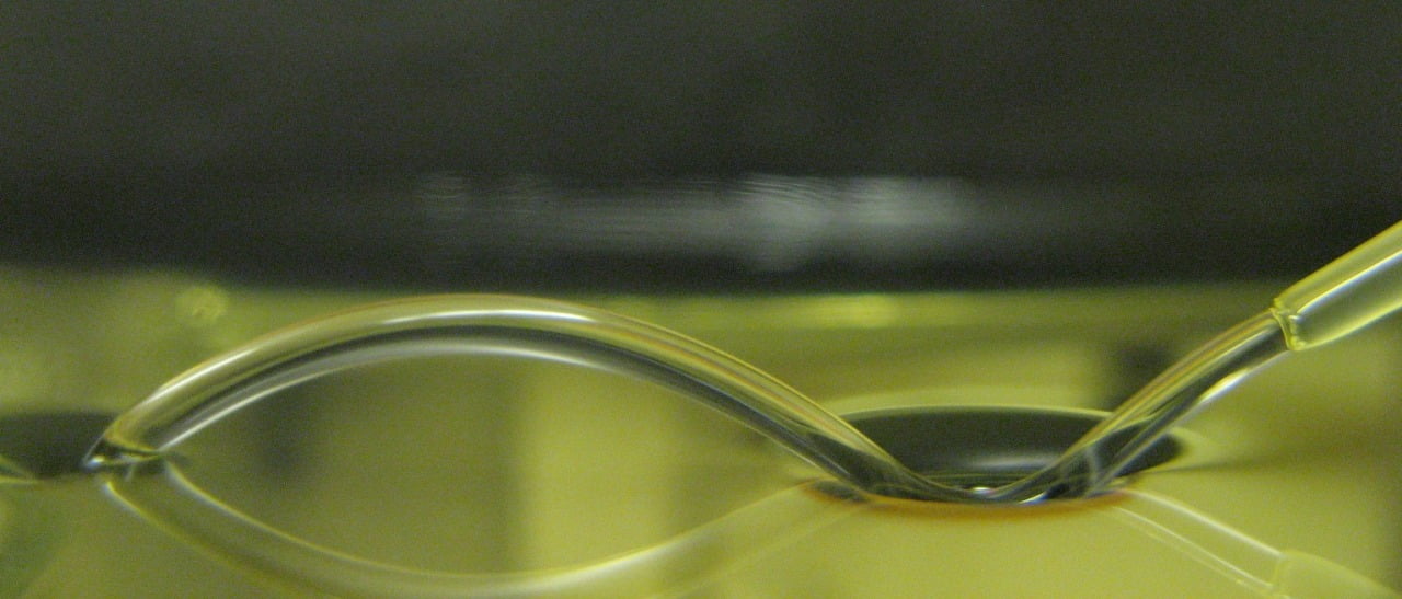
Bouncing Off The Surface
For the right angles and flow rates, it’s possible to bounce a fluid jet off a pool of the same fluid. As the jet flows, it pulls a thin layer of air with it, entraining the air. This air film is what keeps the jet separate from the pool when it initially hits. In the photo above, the jet is flowing right to left; notice how it maintains its integrity within the dimple during the bounce. The pool’s surface tension acts almost like a trampoline, redirecting the jet’s momentum into the bounce. It’s even possible to get a double bounce. In this video, the mechanism is the same, although the apparatus is different. In the photo above, the jet is introduced with a horizontal velocity to induce air entrainment and bouncing. In the video, the pool is spinning, which provides the necessary horizontal velocity between the jet and the liquid pool. (Photo credit: J. Bomber and T. Lockhart)
Liquid Crystal Films
Smectic liquid crystals can form extremely thin films, similar to a soap bubble, that are sensitive to electrically-induced convection. Here an annular smectic film lies between two electrodes. When a voltage is applied across it, positive and negative charges build up on the surface of the film near their respective electrodes. The electrical field surrounding the fluid pushes on the surface charges, causing flow inside the film. Above a threshold voltage, an instability forms and the film develops into a series of counter-rotating vortices, which spin faster as the voltage increases. The color variations in the video above are due to differences in the film’s thickness, much like iridescence of a soap bubble. (Video credit: P. Kruse and S. Morris)
APS DFD etc.
It’s time! The American Physical Society’s Division of Fluid Dynamics meeting opens in Pittsburgh tomorrow morning. It promises to be a very busy few days. Most of that activity will probably not be immediate apparent here on FYFD, but I encourage you to follow along on @fyfluiddynamics, where I’ll be giving a running commentary.
For those attending APS, I have two talks:
- “F*** Yeah Fluid Dynamics: Lessons in online outreach” – Sunday, 5:37pm, Rm 306/307
- “Discrete surface roughness effects on a blunt hypersonic cone in a quiet tunnel” – Tuesday, 1:31pm, Rm 326
I’m looking forward to the chance to meet in person as well, so keep an eye out (I’ll have FYFD stickers on my nametag) and be sure to say hello! There’s been some interest in an informal FYFD get-together, too, so keep an eye on Twitter for that.
Finally, I want to extend my thanks again to all the donors who made it possible for me to get to APS this year. I deeply appreciate your generosity. Special thanks are due to Pointwise, Symscape, and @cenyree for their outstanding support of FYFD! Thank you all again. – Nicole

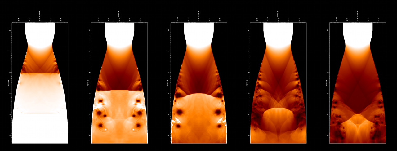
Start Your Rocket Engine
When supersonic flow is achieved through a wind tunnel or rocket nozzle, the flow is said to have “started”. For this to happen, a shock wave must pass through, leaving supersonic flow in its wake. The series of images above show a shock wave passing through an ideal rocket nozzle contour. Flow is from the top to bottom. As the shock wave passes through the nozzle expansion, its interaction with the walls causes flow separation at the wall. This flow separation artificially narrows the rocket nozzle (see images on right), which hampers the acceleration of the air to its designed Mach number. It also causes turbulence and pressure fluctuations that can impact performance. (Image credit: B. Olson et al.)
The Glory of a Roll Cloud
Roll clouds stretch like a long horizontal tube, spinning as they process across the sky. This class of arcus cloud is relatively rare but occasionally forms in areas where cool air is sinking, along the downdraft of an oncoming storm or in coastal regions as a result of sea breezes. The cooler, sinking air displaces warmer, moist air to higher altitudes where the moisture condenses into a cloud. Winds then roll the cloud parallel to the horizon. Roll clouds are a form of soliton, a solitary wave with a single crest that moves without changing its shape or velocity; this is why the cloud appears so regular as it moves across the sky. These clouds are sometimes also called Morning Glory clouds and form regularly off the coast of Queensland, Australia around October. (Video credit: T. and B. Mask)
A reminder, for those attending the APS DFD conference this weekend: my FYFD talk will be Sunday evening at 5:37pm in Rm 306/307. I will be discussing, among other things, the results of July’s reader survey and science communication.

Shocked Interfaces
The Richtmyer-Meshkov instability occurs when two fluids of differing density are hit by a shock wave. The animation above shows a cylinder of denser gas (white) in still air (black) before being hit with a Mach 1.2 shock wave. The cylinder is quickly accelerated and flattened, with either end spinning up to form the counter-rotating vortices that dominate the instability. As the vortices spin, the fluids along the interface shear against one another, and new, secondary instabilities, like the wave-like Kelvin-Helmholtz instability, form along the edges. The two gases mix quickly. This instability is of especial interest for the application of inertial confinement fusion. During implosion, the shell material surrounding the fuel layer is shock-accelerated; since mixing of the shell and fuel is undesirable, researchers are interested in understanding how to control and prevent the instability. (Image credit: S. Shankar et al.)The APS Division of Fluid Dynamics conference begins this Sunday in Pittsburgh. I’ll be giving a talk about FYFD Sunday evening at 5:37pm in Rm 306/307. I hope to see some of you there!
The Challenges of Trapping Carbon Dioxide
One way to reduce carbon dioxide in the atmosphere is to pump the CO2 into saline aquifers deep below the surface. Such aquifers are thin but stretch over large areas and are sometimes gently sloping. Since carbon dioxide is relatively buoyant, it may migrate up-slope after injection and potentially leak elsewhere. Dissolving the carbon dioxide into the groundwater helps prevent this undesirable migration. The video above shows a laboratory analog of the fluid instability at the heart of this trap. Imagine the video tilted by a few degrees so it slopes upward toward the right. The initially buoyant carbon dioxide, represented by the dark fluid, rises on the left and moves rightward, up-slope. As the CO2 dissolves into the ambient groundwater, the water becomes denser and fingers of the CO2-rich water drift downward, effectively halting the carbon dioxide’s escape. This is known as convective dissolution. (Video credit: C. MacMinn and R. Juanes)