A supercritical fluid exists without a distinct liquid or gas phase and forms when temperatures and pressures exceed the substance’s critical point. Here supercritical transition is demonstrated with an ampule of liquid chlorine. When immersed in a hot bath, the temperature and pressure inside the ampule rises until around 0:20 when the meniscus marking the interface between liquid and gas disappears. The chlorine is now in its supercritical state. Around 0:43 the hot bath is removed and the chlorine begins to cool, reverting to distinct phases of matter around 0:55.
Search results for: “transition”
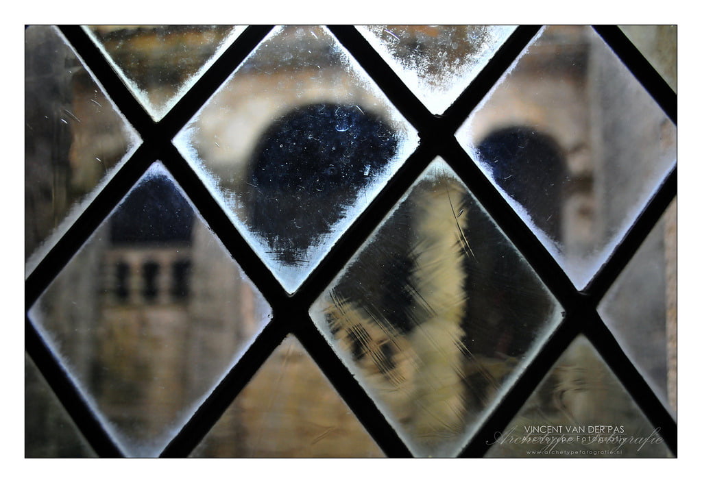
Glass Isn’t a Fluid
Mark R writes:
Glass is a Fluid, Too
Post complex equations regarding how long it would take a certain window to flow, and post pictures of sunken glass. This would be educational.This is a pretty widespread myth. Actually, glass is not a fluid and does not behave like one as long as it is below the glass transition temperature. It’s a bit difficult to classify glass under the traditional categories for a solid due to its phase transition behavior and its lack of crystallization, but it is usually classed as an amorphous solid.
The observation that old panes of glass tend to be thicker at the bottom is usually used as evidence that glass flows over the centuries, but this assumes that the glass was flat to begin with. However, glassblowers at the time usually made panes by spinning molten glass to create a round, mostly even flat, which was then cut to fit. Although spinning made the glass mostly flat, the edges of the disc tended to be thinner. When installed, the glass was typically placed thicker side down for stability purposes. One researcher even calculated the time period necessary for glass to flow and deform at ordinary temperatures as 10^32 years–longer than the age of the universe.
If that is not convincing, consider this: if glass flows at a rate that’s discernible to the naked eye after a couple of centuries, then the effect of this deformation should be extremely noticeable in antique telescopes since a slight change in the lens’ optical properties should dramatically affect performance. But no such degradation occurs. (Photo credit: Vincent van der Pas)

Reader Question: Faucet Physics
jessecaps-blog-deactivated20170 asks:
With respect to the laminar/turbulent flow in the faucet, at the end he explains that the diameter is smaller inside the valve compared to the nozzle and therefore the velocity is greater and turbulence is achieved there before it leaves the nozzle. But turbulence is characterized by the Reynolds number not the velocity, so a larger velocity with a smaller diameter will yield the same Reynolds number, why would we expect turbulence in the nozzle before the stream?
ETA: As pointed out in the comments, I made a very silly mistake when calculating the Reynolds number last night. While most of what I say below is still true in general, it’s not in the case in the faucet, and so I’ve edited the entry to reflect that.
Great question! A quick control volume analysis of an incompressible fluid shows that, while the flow speed is higher through the faucet’s valve, the Reynolds number (based on diameter) at the valve is the same as higher than the Reynolds number at the nozzle by a factor of (nozzle diameter)/(valve diameter). Thus transition can occur at the valve before the nozzle. A word of caution, though: although we often use Reynolds number as a method of characterizing when a flow becomes turbulent, it is not a hard and fast rule.
As undergraduates we learn that pipe flow transitions to turbulence at a Reynolds number of 2,300 based on the pipe’s diameter. However, under the right laboratory conditions, it’s possible to maintain laminar flow in a pipe to a Reynolds number an order of magnitude larger. (#) It all depends on the initial conditions of the flow and the influence of factors like surface roughness. What this means in the case of the faucet is that the same Reynolds number (based on diameter) may not correctly indicate whether the flow is laminar or turbulent at a given point.
Now, while it may be possible that the contraction at the valve introduces some small turbulence that decays prior to the flow’s exit from the nozzle, that does not seem overly likely to me. Even though, by Reynolds number, transition can occur at the valve before the nozzle, I suspect most of the sound we hear comes from the increased flow rate caused by turning the faucet. It may also be that the sound is associated with the onset of turbulence at the valve but the turbulence is still slight enough that we do not notice it by eye in the external flow.
Toroidal Vortex
When instabilities exist in laminar flow, they do not always lead immediately to turbulence. In this video, a viscous fluid fills the space between two concentric cylinders. As the inner cylinder rotates, a linear velocity profile (as viewed from above) forms; this is known as Taylor-Couette flow. If any tiny perturbations are added to that linear profile–say there is a nick in the surface of one of the cylinders–the flow will develop an instability. In this type of flow, an exchange of stabilities will occur. Rather than transitioning to turbulence, the fluid develops a stable secondary flow–the toroidal vortex highlighted by the dye in the video. If the rotation rate is increased further other instabilities will develop.
Propeller Cavitation
Cavitation occurs in moving liquids when the local pressure–in this case, at the tip of the propeller–drops below the vapor pressure. The fast-moving fluid transitions to a gas phase, creating a tip vortex of water vapor even though the propeller is completely submerged.

X-51A Scramjet Test Flight
The X-51A Waverider hypersonic aircraft had its second test flight earlier this week. Unfortunately, its supersonic combustion ramjet (scramjet) engine failed to transition from its start-up fuel to its primary fuel. According to the US Air Force Research Laboratory:
A US Air Force B-52H Stratofortress released the experimental vehicle from an altitude of approximately 50,000 feet. After release the X-51A was initially accelerated by a solid rocket booster to a speed just over Mach 5. The experimental aircraft’s air breathing scramjet engine lit on ethylene and attempted to transition to JP7 fuel operation when the vehicle experienced an inlet un-start. The hypersonic vehicle attempted to restart and oriented itself to optimize engine start conditions, but was unsuccessful. The vehicle continued in a controlled flight orientation until it flew into the ocean within the test range. #
Un-starting is the term used when supersonic flow is lost in an engine or wind tunnel. If the pressure or temperature in the engine deviates too far from the ideal conditions, the upstream mass flow through the engine will be greater than the downstream mass flow and the engine will choke (video). A shock wave forms and travels upstream, leaving subsonic flow in its wake. Loss of supersonic flow inside the engine would likely also result in losing ignition of the fuel/air mixture, resulting in flameout. #
If you haven’t guessed already, engineers like to make up words.
Godspeed, Discovery!
The space shuttle, despite three decades of service, remains a triumph of engineering. Although it is nominally a space vehicle, fluid dynamics are vital throughout its operation. From the combustion in the engine to the overexpansion of the exhaust gases; from the turbulent plume of the shuttle’s wake to the life support and waste management systems on orbit, fluid mechanics cannot be escaped. Countless simulations and experiments have helped determine the forces, temperatures, and flight profiles for the vehicle during ascent and re-entry. Experiments have flown as payloads and hundreds of astronauts have “performed experiments in fluid mechanics” in microgravity. Since STS-114, flow transition experiments have even been mounted on the orbiter wing. The effort and love put into making these machines fly is staggering, but all things end. Godspeed to Discovery and her crew on this, her final mission!

Instability in a Jet
This photo shows the development of a flow instability in an axisymmetric jet. On the left, the jet is smooth and fully laminar, but, by the center of the photo, disturbances in the jet have grown large enough to distort the laminar profile. The jet is then in transition; by the right side of the frame, it has reached a turbulent state, as evidenced by the increased mixing (which causes the smoke to disperse more quickly) and intermittency of the flow. #
Wavy Vortices
Shown above is the flow between two concentric cylinders (Taylor-Couette flow). In the laminar regime, the velocity profile between the two cylinders is linear. As the rate of rotation of the inner cylinder increases, the flow develops toroidal vortices known as Taylor vortices, seen in the video above after 9 seconds or so. This is a fluid instability exhibited by transitional flow. Increasing the rotational rate further can result in wavy Taylor vortex flow. At high enough speeds, the flow will become completely turbulent.

Three Flows in One
These plumes of smoke demonstrate the three types of fluid flow: laminar, transitional, and turbulent. At the bottom of the photo, the plumes are smooth and orderly, as is typical for laminar flow. At the top, the smoke’s movement is chaotic and intermittent, full of turbulent eddies. Between these two stages, the flow is in transition; there is still some semblance of order to it, but disturbances in the plume are getting amplified and breaking down into turbulence.
Photo credit: J. Russo