

Although you may not recognize the name, you’ve probably seen Kalliroscope (top image), a pearlescent fluid that creates beautiful flow patterns when swirled. This rheoscopic fluid was invented in the mid-1960s by artist Paul Matisse and, over the following decades, became a staple of flow visualization techniques. Kalliroscope contained a suspension of crystalline guanine. Since the crystals were asymmetric, they would orient themselves depending on the flow and, from there, scatter light, creating the beautiful pearlescent effect seen above.
Unfortunately for researchers, the production of guanine crystals was expensive and difficult. The cosmetics industry was their main consumer and over time, they moved toward mica and other cheaper mineral alternatives. The company that produced Kalliroscope gave up production in 2014, leaving researchers scrambling for a suitable alternative.
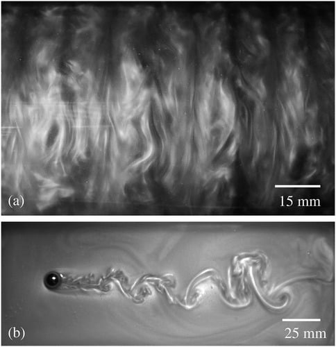
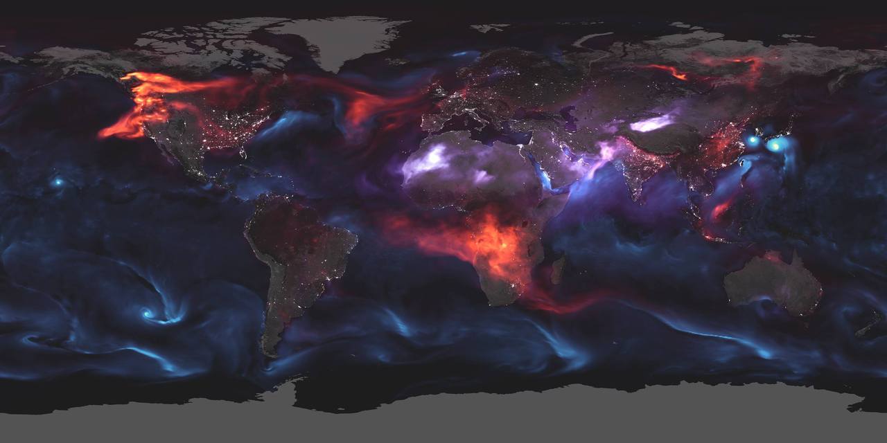
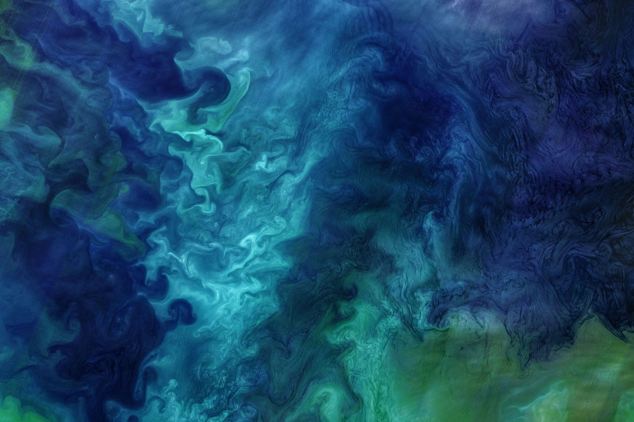
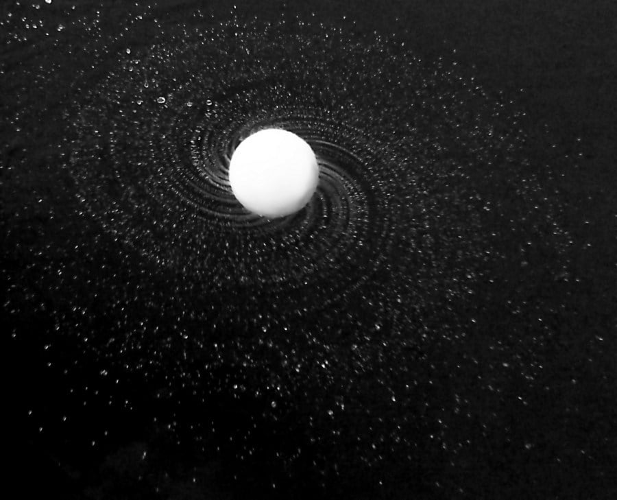
One contender for a new standard rheoscopic fluid is based on shaving cream. By diluting shaving cream 20:1 with water, researchers are able to extract stearic acid crystals, which form an admirable alternative to Kalliroscope (middle collage). Like Kalliroscope, the resulting fluid is pearlescent and reveals flow features well (bottom two images). Stearic acid crystals are also closer in density to water than guanine, so the fluid remains in suspension far better than Kalliroscope. Plus, the best shaving cream is cheap and widely available, meaning that this is a DIY project just about anyone can do! (Image credits: Kalliroscope – P. Matisse; other images – D. Borrero-Echeverry et al.; research credit: D. Borrero-Echeverry et al.)


