Tag: flow separation

  • PyeongChang 2018: Speedskating

    PyeongChang 2018: Speedskating

    Four years ago in Sochi, Under Armour’s suits for the U.S. speedskating team took a lot of flak after the team failed to medal. The company defended the physics and engineering of their suits, and an internal audit of the speedskating program ultimately placed blame on flaws in their training regimen, unfamiliarity with the new suits, and overconfidence.

    This time around Under Armour has taken a more hands-on approach with the team, helping with training regimens in addition to providing suits. Under Armour spent hundreds of hours testing the suits in Specialized’s wind tunnel, including testing many fabrics before settling on the slightly rough H1 fabric used in patches on the skater’s arms and legs. Like the previous suit’s dimpled design, the roughness of the fabric promotes turbulent flow near it. Because turbulent flow follows curved contours better than laminar flow does, air stays attached to the athlete for longer, thereby reducing their drag. The suit is also designed with asymmetric seams that help the athlete stay low and comfortable in the sport’s frequent left turns.

    U.S. speedskaters have been competing in a version of the suits since last winter, ensuring that athletes are familiar with the equipment this time around. Whether the new suits and training program will pay off remains to be seen. After their disastrous experience in Sochi, both the team and the company are shy about setting expectations. (Image credits: D. Maloney/Wired; US Speedskating)

  • Withstanding Windstorms

    Withstanding Windstorms

    Saguaro cacti can grow 15 meters tall, and despite their shallow root systems can withstand storm winds up to 38 meters per second without being blown over. Grooves in the cacti’s surface may contribute to its resilience, by adding structural support and/or through reducing aerodynamic loads. The latter theory mirrors the concept of dimples on a golf ball; namely, grooves create turbulence in the flow near the cactus, which allows air flow to track further around the cactus before separating. The result is less drag for a given wind speed than a smooth cactus would experience.

    Indeed, recent experiments on a grooved cylinder with a pneumatically-controlled shape showed exactly that; the morphable cylinder’s drag was consistently significantly lower than fixed samples. Cacti do change their shapes somewhat as their water content changes, but they don’t have the ability for up-to-the-minute alterations. Nevertheless, their adaptations can inspire engineered creations that morph to reduce wind impact. (Image credit: A. Levine; research credit: M. Guttag and P. Reis)

  • Delta Wing Flow Viz

    Delta Wing Flow Viz

    Designing new aerodynamic vehicles typically requires a combination of multiple experimental and numerical techniques. The photo above shows a model for an unmanned flying wing-type vehicle. Here it’s tested in a water tunnel with dye introduced to the flow to highlight different areas. The model is at a high angle of attack (18 degrees) relative to the oncoming flow. This puts it in danger of flow separation and stall, the point where a wing experiences a drastic loss in lift. The smooth flow over the front of the model indicates it hasn’t reached this point yet, but notice how both the green and red dyes are separating from the model and becoming very turbulent over the back of the wing. If the model were pushed to an even higher angle of attack, that separation point would move further forward, bringing stall that much closer. (Image credit: L. Erm and J. Drobik; research credit: R. Cummings and A. Schütte)

  • Cycling Skinsuits and Vortex Generators

    Cycling Skinsuits and Vortex Generators

    It didn’t take long for an aerodynamic controversy to crop up in this year’s Tour de France. At the 14km individual time trial, riders from Team Sky wore custom Castelli skinsuits with integrated dot-like patterns on their upper arms (shown above). By the next day, a sports scientist with a competing team cried foul play, claiming that these fabrics could have given Team Sky as much as 25 seconds’ advantage over other riders. The Sky team finished with 4 out of the top 10 places on the time trial, and their leader, three-time Tour winner Chris Froome, finished some 35 seconds ahead of his expected competitors for the yellow jersey.

    Vortex generators explained

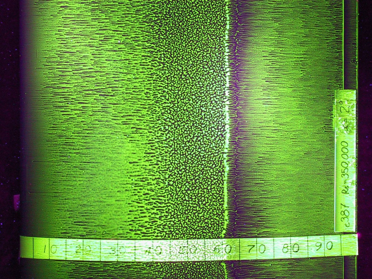
    So how could a few dots make a measurable difference? These protrusions are vortex generators meant to modify flow around a cyclist. Humans are not aerodynamic and what typically happens when air flows over a cyclist’s arms is shown in the flow visualization above: the air follows the curve of the arm part way, then it separates from the body, leaving a region of recirculation that increases drag. Vortex generators can help prevent or delay that drag-inducing flow separation by adding extra energy and turbulence to the air near the arm’s surface. Because turbulent boundary layers can follow a curve longer before separating, this helps reduce the drag by reducing the recirculation zone.

    About that time savings

    Aerodynamically speaking, those vortex generators can make a difference, but the question is, how much? In his complaint, Grappe cites a 2016 paper by L. Brownlie et al. that wind-tunnel tested different vortex generator patterns for use in running apparel. The speeds tested included those relevant to cycling. The specific numbers Grappe quotes aren’t directly relevant, however:

    As noted above, race garments that contain VG provide reductions in Fd of between 3.7 and 6.8% compared to equivalent
    advanced race apparel developed for the 2012 London Olympics which in turn provided substantially lower drag than
    conventional race apparel.

    the effectiveness of 5, 10 and 15 cm wide strips of VG applied to each flank of a sleeveless singlet revealed that the 5 cm wide
    strips provided between 3.1 and 7.1% less Fd than the 10 cm wide strips and between 1.9 and 4.3% less Fd than the 15 cm wide
    strips.  

    Here Brownlie et al. are specifically describing the savings for running apparel, which uses vortex generators in very different places than you would on a cyclist. Note the second quote even refers to a sleeveless singlet, so the vortex generators measured are definitely not in the same place as these skinsuits!

    The bottom line

    I fully expect that vortex generators give a marginal aerodynamic edge, which is why Sky and other teams have already been using them in competition. But I hesitate to declare that the savings is as high as 5-7%, and I have no way to verify Grappe’s subsequent claims that this translates to 18-25 seconds in the time trial. Those are numbers he gives without citing what model is being used to translate drag gains into time.

    In the end, what is needed is clarification of the rules. As they stand, one rule seems to allow the skinsuits because the vortex generators are integrated into the fabric, whereas another states clothing is forbidden “to influence the performances of a rider such as reducing air resistance”. Those two stances seems contradictory, and, for now, the race officials’ verdict to allow the suits stands.

    If you want to learn more about aerodynamics and cycling, be sure to check out my latest FYFD video. (Image credits: B. Tessier/Reuters; Getty Images; L. Brownlie et al. 2009; h/t to W. Küper)

  • Rio 2016: Table Tennis

    Rio 2016: Table Tennis

    Many sports use spherical balls, but the small size and weight of a table tennis ball makes it the one where aerodynamics have the strongest effect. Spin also plays a big role in the game by creating asymmetry in the flow around the ball. 

    Consider a table tennis ball with topspin, meaning that its upper surface is rolling in the direction of travel. That means that air flowing over the top of the ball is moving in the opposite direction as the ball’s surface. This will tend to make the flow separate from the ball at its widest point. 

    On the other side, the ball’s surface is spinning in the same direction as the air flow. This helps hold the air to the surface so that it follows the curve of the ball longer and doesn’t detach until well after the ball’s widest point. As a result of both these effects, air flowing around the ball experiences a net upward force, which in turn pushes the table tennis ball downward. This is known as the Magnus effect, and it plays a significant role in many sports.   (Image credits: GettyImages; AFP)

    Previously:  The Magnus effect and the reverse Magnus effect in soccer; curveballs and knuckleballs in baseball 

    Join us throughout the Rio Olympics for more fluid dynamics in sports. If you love FYFD, please help support the site!

  • Plasma Flow Control

    Plasma Flow Control

    Engineers frequently face the challenge of maintaining control of air flow around an object across a wide range of conditions. After all, wind turbines and airplanes don’t always get to choose the perfect weather. To widen their operating ranges, designers can use active flow control to keep air flowing around an airfoil instead of separating and causing stall. One method of flow control uses plasma actuators on the upper surface of an airfoil. When activated, the plasma actuator ionizes air near the wing surface, producing the purplish glow seen above. That ionized air, or plasma, gets accelerated by the electric field of the device. The acceleration adds momentum to air near the wing surface, which helps it stay attached and flowing smoothly despite the unfavorable pressure conditions near the trailing edge of the wing. Compared to other methods of active flow control, plasma actuation is relatively simple to implement and so is actively being researched for applications in aviation and wind energy. (Image and research credit: I. Brownstein et al., source)

  • The Challenges of Micro Air Vehicles

    The Challenges of Micro Air Vehicles

    Interest in micro-aerial vehicles (MAVs) has proliferated in the last decade. But making these aircraft fly is more complicated than simply shrinking airplane designs. At smaller sizes and lower speeds, an airplane’s Reynolds number is smaller, too, and it behaves aerodynamically differently. The photo above shows the upper surface of a low Reynolds number airfoil that’s been treated with oil for flow visualization. The flow in the photo is from left to right. On the left side, the air has flowed in a smooth and laminar fashion over the first 35% of the wing, as seen from the long streaks of oil. In the middle, though, the oil is speckled, which indicates that air hasn’t been flowing over it–the flow has separated from the surface, leaving a bubble of slowly recirculating air next to the airfoil. Further to the right, about 65% of the way down the wing, the flow has reattached to the airfoil, driving the oil to either side and creating the dark line seen in the image. Such flow separation and reattachment is common for airfoils at these scales, and the loss of lift (and of control) this sudden change can cause is a major challenge for MAV designers. (Image credit: M. Selig et al.)

  • Featured Video Play Icon

    Magnus Effect

    Putting a little bit of spin on an object can have a big aerodynamic effect, thanks to the Magnus effect. As demonstrated in the video above, backspin on a basketball dropped from a big height will send it flying out and away. The reason spinning objects generate these counterintuitive motions is because the air flow over them creates differential pressures. On the side of the ball spinning with the flow, air is accelerated, dropping the local pressure; whereas on the opposite side, the ball spinning against the direction of flow makes the flow separate and no longer flow smoothly along that side. This causes a high pressure on that side. Like the difference in pressure on either side of an airfoil, the pressure difference across the ball creates a force that pushes the ball toward the low pressure side. Check out some of the other places Magnus effect shows up!  (Video credit: Veritasium; submitted by Andrew C.)

    ——————

    Help us do some science! I’ve teamed up with researcher Paige Brown Jarreau to create a survey of FYFD readers. By participating, you’ll be helping me improve FYFD and contributing to novel academic research on the readers of science blogs. It should only take 10-15 minutes to complete. You can find the survey here.

  • Turbine Blade Separation

    [original media no longer available]

    Maintaining consistent air flow along the contours of an object is key to aerodynamic efficiency. When air flow separates or forms a recirculation zone, the drag increases and efficiency drops. On wind turbine blades, flow often separates on the root end of the blade near its attachment point. This behavior is apparent in the video above at 0:34. The tufts in the foreground on the turning blade flap and flutter with no clear pattern because the air flow has separated from the surface. In the subsequent clip, a line of vortex generators has been attached near the leading edge of the blade. These structures–also commonly seen on airplanes–trail vortices behind them, mixing the flow and generating a turbulent boundary layer which is better able to resist flow separation. The effect on the flow is clear from the tufts, most of which now point in a consistent direction with little to no fluttering, indicating that the air flow has remained attached. (Video credit: Smart Blade Gmbh/Technische Universität Berlin)

    (Source: /)
  • Transonic Flow

    Transonic Flow

    In the transonic speed regime the overall speed of an airplane is less than Mach 1 but some parts of the flow around the aircraft break the speed of sound. The photo above shows a schlieren photograph of flow over an airfoil at transonic speeds. The nearly vertical lines are shock waves on the upper and lower surfaces of the airfoil. Although the freestream speed in the tunnel is less than Mach 1 upstream of the airfoil, air accelerates over the curved surface of airfoil and locally exceeds the speed of sound. When that supersonic flow cannot be sustained, a shock wave occurs; flow to the right of the shock wave is once again subsonic. It’s also worth noting the bright white turbulent flow along the upper surface of the airfoil after the shock. This is the boundary layer, which can often separate from the wing in transonic flows, causing a marked increase in drag and decrease in lift. Most commercial airliners operate at transonic Mach numbers and their geometry is specifically designed to mitigate some of the challenges of this speed regime.  (Image credit: NASA; via D. Baals and W. Corliss)