Although eyes are common at the center of large-scale cyclones, scientists are only now beginning to understand how they form. Since real-world cyclogenesis is complicated by many competing effects, researchers look at simplified model systems first. A typical one uses a shallow, rotating cylindrical domain in which heat rises from below. The rotation provides a Coriolis force, which shapes the flow. In particular, it causes a boundary layer along the lower surface of the domain, creating a thin region where the flow moves radially inward. (Its opposite forms at the upper surface of the domain, sending flow radiating outward.) Like an ice skater spinning, the flow’s vorticity intensifies as it approaches the central axis of rotation. When the conditions are right, this intensely swirling boundary layer flow lifts up into the main flow, forming an eyewall. The eye itself, it turns out, is merely a reaction to the eyewall’s formation. (Image credit: S. Cristoforetti/ESA; research credit: L. Oruba et al.)
Tag: boundary layer

Reducing Drag with Bubbles
Large ships experience a great deal of drag due to friction between their hull and the water. One method shipbuilders are considering to combat this drag is the use of bubbles, which have been found to reduce drag by up to 40%. The physical mechanism behind this drag reduction is not yet understood, but a recent study suggests that bubble size and bubble coalescence play an important role.
Researchers introduced surfactants into bubbly boundary layers and found that the reductions in drag evaporated as soon as the surfactants spread. Adding only 6 parts per million of the surfactant decreased average bubble size from 1 mm to 0.1 mm and helped prevent the bubbles from growing via coalescence. The implications are that bubble-induced drag reduction could be extremely sensitive to water conditions. (Image credit: G. Kiss; research credit: R. Verschoof et al.)

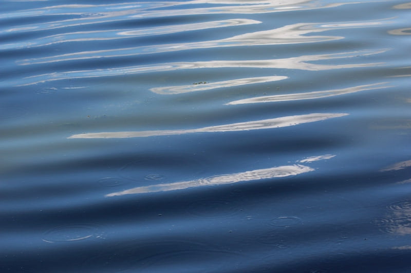
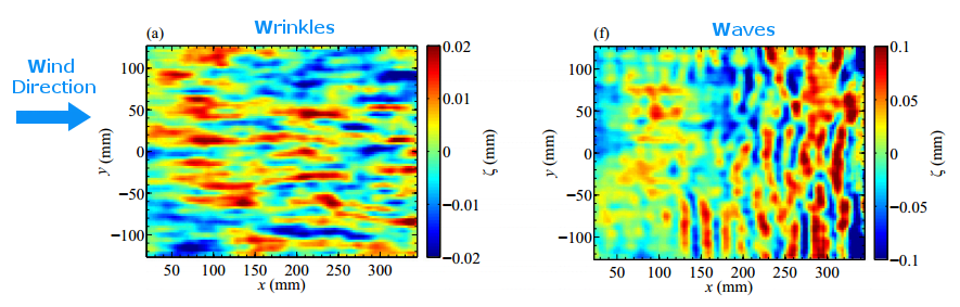
Wrinkling Winds

If you’ve ever sat out on a lake and just watched the water’s surface, you’ve probably noticed how complex and variable it looks. There may be waves that rock your kayak but there are smaller variations, too, like little ripples or even tiny wrinkles that appear on the surface. Much of this activity comes from wind blowing across the water. When the wind exceeds a critical speed, waves form. They generally travel in lines that are aligned perpendicular to the wind (lower right). But what happens when the wind is below the critical speed?
A recent study looked at just this question. By blowing air across the surface of different liquids and observing variations in the surface height as small as 2 micrometers, the researchers were able to measure tiny wrinkles on the water’s surface (lower left) when the wind speed was small. The size and shape of the wrinkles actually corresponds to structures in the turbulent air flow over the water! For fluids like water, there’s a smooth transition from wrinkles to waves as the wind speed increases, so both may be visible at the same time. For higher viscosity fluids, the switch from one to the other is more abrupt. (Image credits: water – M. Soveran; figure – A. Paquier et al. w/ annotations added in blue; research credit: A. Paquier et al.)

HIFiRE


Earlier this month, an international team launched a successful hypersonic flight test in Australia. The Hypersonic International Research Experimentation (HIFiRE) Flight 5b was launched atop a two-stage rocket and reached its maximum speed of Mach 7.5, well above Mach 5, which defines the start of the hypersonic regime. The purpose of this particular flight test was not to test new propulsion technologies – there was no scramjet engine on this flight. Instead, researchers wanted to study aerodynamics at high Mach number, specifically the behavior of the air very close to the vehicle, its boundary layer.
The payload being tested was an elliptical cone mounted on the front of the vehicle and shown in images above. The shape of the payload is such that flow will curve around the cone rather than following straight lines. The image on the lower right contains black streamlines that show how air twists around the cone. This complex flowfield complicates the physics of the boundary layer near the cone’s surface and increases the likelihood that the boundary layer will transition from laminar flow to turbulent flow, thereby increasing heating on the payload. Ideally, the data from the test flight will let engineers test their ability to understand and predict this boundary layer transition in the future. For more on boundary layer transition and its effects at hypersonic speeds, check out my latest FYFD video. (Image credit: Australia Department of Defense, R. Kimmel et al., F. Li et al.; topic requested by Guido)

The Reverse Magnus Effect
A good soccer player can kick the ball from the corner of the field into the goal thanks to the Magnus effect. But if you’ve ever tried to play soccer with a smooth ball, you may have noticed that sometimes the ball bends the wrong way! This is the reverse Magnus effect and it’s caused when the boundary layers on either side of the ball switch from turbulent to laminar flow at different times. Dianna Cowern explains (with a little help from yours truly) in the video above. Want to learn more about how roughness affects boundary layers? Check out our companion video on FYFD’s YouTube channel. (Video credit: D. Cowern/Physics Girl)
How Fluid Dynamics Saved the Space Shuttle
New FYFD video! In which Dianna Cowern (Physics Girl) joins me to explore boundary layer transition and how a couple of small bits of roughness could be a huge problem for the Space Shuttle during re-entry. A lot of people have asked me what I did for my PhD research, and the truth is, I’ve never really discussed my own work here on FYFD. This video is probably the closest I’ve come. The story I tell about STS-114 is one that appears in the first chapter of my dissertation, and it did, in many respects, motivate my work exploring roughness effects on transition in Mach 6 boundary layers. I hope you enjoy my video, and don’t forget to check out Dianna’s video, too! (Video credit: N. Sharp/FYFD)

Plasma Flow Control

Engineers frequently face the challenge of maintaining control of air flow around an object across a wide range of conditions. After all, wind turbines and airplanes don’t always get to choose the perfect weather. To widen their operating ranges, designers can use active flow control to keep air flowing around an airfoil instead of separating and causing stall. One method of flow control uses plasma actuators on the upper surface of an airfoil. When activated, the plasma actuator ionizes air near the wing surface, producing the purplish glow seen above. That ionized air, or plasma, gets accelerated by the electric field of the device. The acceleration adds momentum to air near the wing surface, which helps it stay attached and flowing smoothly despite the unfavorable pressure conditions near the trailing edge of the wing. Compared to other methods of active flow control, plasma actuation is relatively simple to implement and so is actively being researched for applications in aviation and wind energy. (Image and research credit: I. Brownstein et al., source)

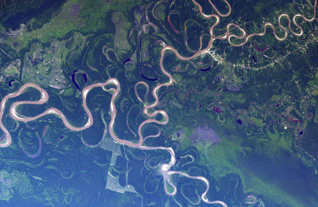
Meander from Above
This photo of the Amazon River taken by Astronaut Tim Kopra reveals the many meandering changes of the river’s course. Left untouched by human intervention, rivers tend to get more curvy, or sinuous, over time, simply due to fluid dynamics. Imagine a single bend in a river. Due to conservation of angular momentum, water flows faster around the inside curve of the bend than the outside – just like an ice skater spins faster with her arms pulled in. From Bernoulli’s principle, we know there is an accompanying pressure gradient caused by this velocity difference – with higher pressure near the outer bank and lower pressure on the inner one. This pressure gradient is what guides the water around the bend, keeping the bulk of the fluid moving downstream rather than bending toward either bank.
At the bottom of the river, though, viscosity slows the water down due to the influence of the ground. This slower water, still subject to the same pressure gradient as the rest of the river, cannot maintain its course going downstream. Instead, it gets pushed from the outer bank toward the inner bank in what’s known as a secondary flow. This secondary flow carries sediment away from the outer bank and deposits it on the inner bank, which, over time, makes the river bend more and more pronounced. (Image credit: T. Kopra/NASA; submitted by jshoer)
Do you enjoy FYFD and want to help support it? Then please consider becoming a patron!
City Winds Simulated
Anyone who has spent much time in an urban environment is familiar with the gusty turbulence that can be generated by steady winds interacting with tall buildings. To the atmospheric boundary layer–the first few hundred meters of atmosphere just above the ground–cities, forests, and other terrain changes act like sudden patches of roughness that disturb the flow and generate turbulence. The video above shows a numerical simulation of flow over an urban environment. The incoming flow off the ocean is relatively calm due to the smoothness of the water. But the roughness of an artificial island just off the coast acts like a trip, creating a new and more turbulent boundary layer within the atmospheric boundary layer. It’s this growing internal boundary layer whose turbulence we see visualized in greens and reds. (Video credit: H. Knoop et al.)

Transonic Flow
In the transonic speed regime the overall speed of an airplane is less than Mach 1 but some parts of the flow around the aircraft break the speed of sound. The photo above shows a schlieren photograph of flow over an airfoil at transonic speeds. The nearly vertical lines are shock waves on the upper and lower surfaces of the airfoil. Although the freestream speed in the tunnel is less than Mach 1 upstream of the airfoil, air accelerates over the curved surface of airfoil and locally exceeds the speed of sound. When that supersonic flow cannot be sustained, a shock wave occurs; flow to the right of the shock wave is once again subsonic. It’s also worth noting the bright white turbulent flow along the upper surface of the airfoil after the shock. This is the boundary layer, which can often separate from the wing in transonic flows, causing a marked increase in drag and decrease in lift. Most commercial airliners operate at transonic Mach numbers and their geometry is specifically designed to mitigate some of the challenges of this speed regime. (Image credit: NASA; via D. Baals and W. Corliss)