Tag: aircraft

  • Aboard a Hurricane Hunter

    Aboard a Hurricane Hunter

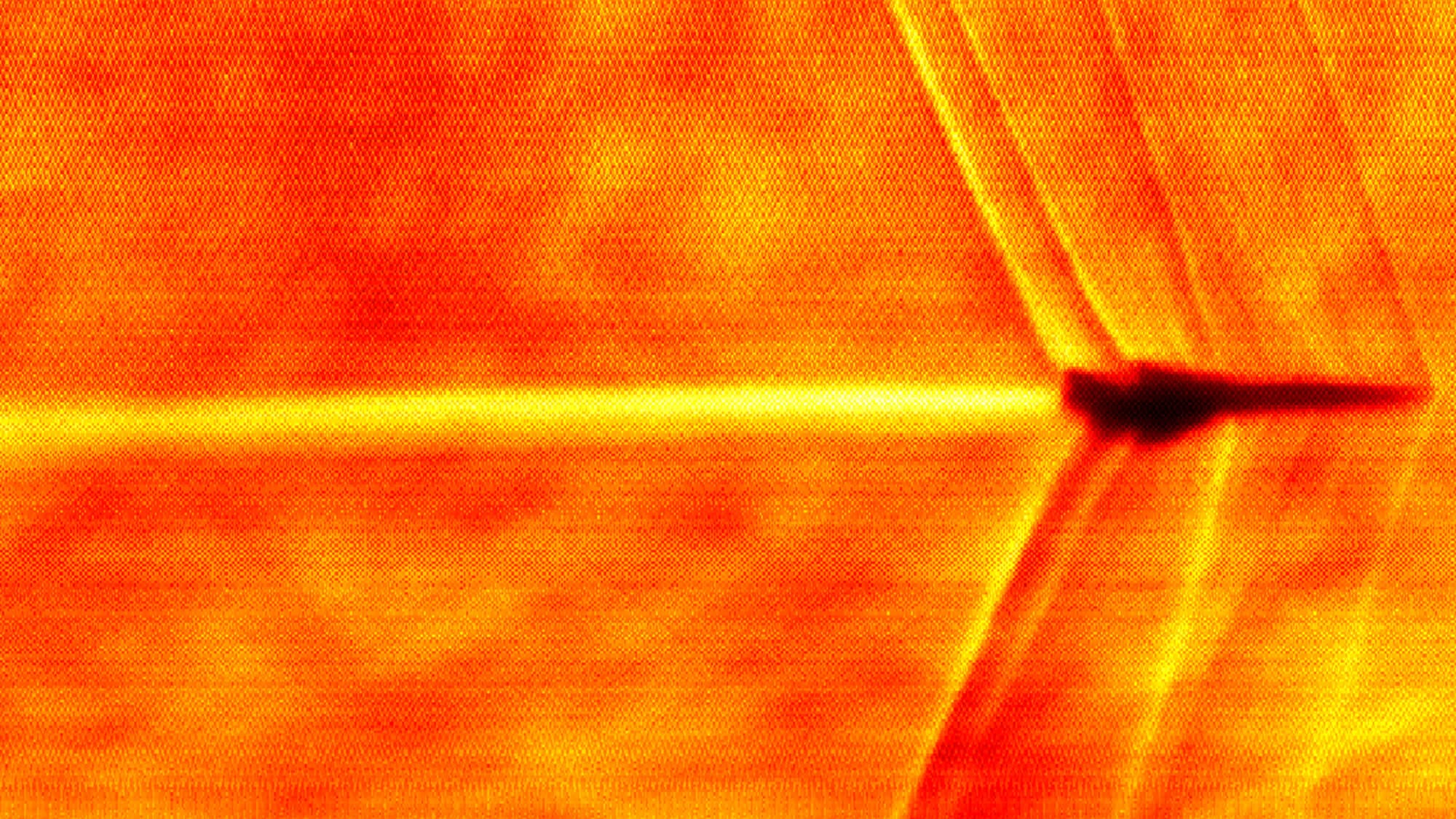
    For decades, NOAA has relied on two WP-3D Orion aircraft–nicknamed Kermit and Miss Piggy–to carry crews into the heart of hurricanes, collecting data all the while. Every ride aboard a Hurricane Hunter is a bumpy one, but some flights are notorious for the level of turbulence they see. In a recent analysis, researchers used flight data since 2004 (as well as a couple of infamous historic flights) to determine a “bumpiness index” that people aboard each flight would experience, based on the plane’s accelerations and changes in acceleration (i.e., jerk).

    The analysis confirmed that a 1989 flight into Hurricane Hugo was the bumpiest of all-time, followed by a 2022 flight into Hurricane Ian, which was notable for its side-to-side (rather than up-and-down) motions. Overall, they found that the most turbulent flights occurred in strong storms that would weaken in the next 12 hours, and that the bumpiest spot in a hurricane was on the inner edge of the eyewall. That especially turbulent region, they found, is associated with a large gradient in radar reflectivity, which could help future Hurricane Hunter pilots avoid such dangers. (Image credit: NOAA; research credit: J. Wadler et al.; via Eos)

    Fediverse Reactions
  • Imaging a New Era of Supersonic Travel

    Imaging a New Era of Supersonic Travel

    Supersonic commercial travel was briefly possible in the twentieth century when the Concorde flew. But the window-rattling sonic boom of that aircraft made governments restrict supersonic travel over land. Now a new generation of aviation companies are revisiting the concept of supersonic commercial travel with technologies that help dampen the irritating effects of a plane’s shock waves.

    One such company, Boom Supersonic, partnered with NASA to capture the above schlieren image of their experimental XB-1 aircraft in flight. The diagonal lines spreading from the nose, wings, and tail of the aircraft mark shock waves. It’s those shock waves’ interactions with people and buildings on the ground that causes problems. But the XB-1 is testing out scalable methods for producing weaker shock waves that dissipate before reaching people down below, thus reducing the biggest source of complaints about supersonic flight over land. (Image credit: Boom Supersonic/NASA; via Quartz)

    The XB-1 test aircraft in flight.
    Fediverse Reactions
  • Sonic Booms and Urban Canyons

    Sonic Booms and Urban Canyons

    In the days of the Concorde — thus far the world’s only supersonic passenger jet — noise complaints from residents kept the aircraft from faster-than-sound travel except over the open ocean. With many pursuing a new generation of civil supersonic aircraft, researchers are looking at how those sonic booms could interact with those of us on the ground.

    In this study, researchers simulated the shock waves from aircraft interacting with single and multiple buildings on the ground. They found that the presence of a building increases the perceived sound level of the boom by about 7 dB at the most. But the most interesting results are what happens between multiple buildings.

    If the street between buildings is wide enough, they each act independently, as if they were single buildings. But for narrower streets, the acoustics waves reflect and diffract between the buildings, creating a resonance that makes the acoustic echoes last longer. The effect is especially pronounced for a sonic boom traveling across a series of buildings, which mimics the layout of a dense city full of urban canyons. (Image credit: Concorde – M. Rochette, simulation – D. Dragna et al.; research credit: D. Dragna et al.)

    Acoustic waves reflect and propagate through 2D urban canyons with widths of 10 meters (top), 20 meters (middle), and 30 meters (bottom).
    Acoustic waves reflect and propagate through 2D urban canyons with widths of 10 meters (top), 20 meters (middle), and 30 meters (bottom).
  • Vortices and Ground Effect

    Vortices and Ground Effect

    Though typically unseen, the vortices that swirl from the tips of aircraft wings are powerful. Here you see a Hawker Sea Fury equipped with a smoke system used to visualize the vortices that form at the wingtip as high-pressure air from the bottom of the wing and low-pressure air from the top swirl together. As you can see, the vortices persist in the wake long after the plane passes. The size and strength of the vortices depend on the size and speed of the aircraft; this is why air traffic control requires smaller planes to wait longer to take off or land if there was just a larger aircraft on the runway.

    The other cool thing to note here is how the wingtip vortices move apart from one another in the animation above. In flight, wingtip vortices usually stay roughly parallel to one another, but they drift downward in the aircraft’s wake. Near the ground, though, the vortices cannot move down, so instead ground effect forces them apart from one another, as seen here. (Image and video credit: E. Seguin; via Kelsey C.)

  • Featured Video Play Icon

    Bounce or Freeze?

    Icing is a major problem for aircraft.  When ice builds up on the leading edge of a wing it creates major disruptions in flow around the wing and can lead to a loss of flight control. One of the important factors in predicting and controlling ice building up is knowing when and where water droplets will freeze. The video above shows how surface conditions on the wing affect how an impacting droplet freezes. On a subzero hydrophilic surface, a falling droplet spreads and freezes over a wide area, which would hasten ice buildup. A hydrophobic surface is slightly better, with the droplet freezing over a smaller area, whereas a superhydrophobic surface shows no ice buildup. Unfortunately, at present superhydrophobic surfaces and surface treatments are extremely delicate, making them unsuitable for use on aircraft leading edges. (Video credit: G. Finlay)

  • Turbojet Engines

    [original media no longer available]

    GE has a great new video with a straightforward explanation of the turbojet and the turbofan engines. The simplest description of the engines–suck, squeeze, bang, blow–sounds like a euphemism but it’s fairly accurate. The engines draw in air, compress it by making it flow through a series of small rotating blades, add fuel and combust the mixture, pull out energy through a turbine, and then blow the high-speed exhaust out the back to generate thrust. The thrust is key because it’s the force that overcomes drag on the plane and also generates the speed needed to create lift. There are two ways to significantly increase thrust: a) increase the mass flow rate of air through the engine, and/or b) increase the exhaust velocity. The turbojet engine draws in smaller amounts of air but generates very high exhaust velocities. The turbofan is today’s preferred commercial aircraft engine because it can generate thrust more efficiently at the desired aircraft velocity. The turbofan essentially has a turbojet engine in its center and is surrounded by a large air-bypass. Most of the air passing through the engine flows through the bypass and the fan. This increases its velocity only slightly, but it means that the engine accelerates much larger amounts of air without requiring much larger amounts of fuel. As an added bonus, the lower exhaust velocities of the turbofan engine make it much quieter in operation. (Video credit: General Electric)

  • Wing-Warping

    Wing-Warping

    This replica of the Wright brothers’ 1902 glider demonstrates one of the important innovations the brothers contributed toward powered heavier-than-air flight. To control an aircraft in roll, the Wright brothers developed the idea of wing-warping. The pilot would lie in the cradle (center of image) and shift his body to one side. A system of wires and pulleys would then twist the wings from their rear edge, pulling one side down and the other up. This deflection is akin to changing the wing’s angle of attack. Deflecting the right wingtip downward increased the lift on the right side of the glider, while simultaneously the upward deflection on the left decreased the lift on that side. This causes the glider to bank, or roll, with the right wing up, thereby generating a leftward turn. The lift differential also caused a drag differential, though, with increased drag on the lifted (right, in this case) wing. That extra drag tended to pull the aircraft’s nose rightward, a condition known as adverse yaw. To counter it, the Wright brothers installed a steerable rudder and linked it to the wing-warping mechanism, allowing them to turn with much less effort than other conventional craft. Although wing-warping has been replaced with ailerons, the control principles remain the same. For more, watch this demo of the wing warping mechanism on a 1903 Wright Flyer replica. (Image credit: C. Devers)