This infrared image shows a kilometer-high volcanic vortex swirling over the Bardarbunga eruption. The bright red at the bottom is lava escaping the fissure, whereas the yellow and white regions show rising hot gases. Although the vortex looks similar to a tornado, it is actually more like a dust devil or a so-called fire tornado. All three of these vortices are driven by a heat source near the ground that generates buoyant updrafts of air. As the hot gases rise, cooler air flows in to replace them. Any small vorticity in that ambient air gets amplified as it’s drawn to the center, the same way an ice skater spins faster when she pulls her arms in. With the right conditions, a vortex can form. Unlike a harmless dust devil, though, this vortex is likely filled with sulphur dioxide and volcanic ash and would pose a serious hazard to aviation. (Image credit: Nicarnica Aviation; source video; via io9)
Tag: science

Reconfigurable Liquid Metal
Terminator 2’s T-1000, a liquid metal robot capable of changing its shape at will, just became a little less far-fetched. Researchers at NC State have reported a new method for controlling the form of a liquid gallium alloy. Surface tension governs the shape a liquid assumes when it is not confined by a container, and, although adding surfactants can slightly lower the surface tension, it does not substantially alter the liquid’s shape. Adding soap to water lets one make bubbles, but surface tension keeps the bubbles spherical no matter how much soap you add. Instead, these researchers control the surface tension of the liquid metal using a mild voltage. Applying a voltage creates (or removes) an oxide layer on the liquid metal’s surface, thereby altering the surface tension. By controlling the formation of the oxide layer, the researchers can change the surface tension from approximately 7x that of water to nearly zero. The video above demonstrates some of the liquid shape control this lets them achieve. (VIdeo credit: M. Dickey et al.; research: M. Khan et al.; via PopSci)

Beading Fluids
Adding just a few polymers to a liquid can substantially change its behavior. The presence of polymers turns otherwise Newtonian fluids like water into viscoelastic fluids. When deformed, viscoelastic fluids have a response that is part viscous–like other fluids–and part elastic–like a rubber band that regains its initial shape. The collage above shows what happens to a thinning column of a viscoelastic fluid. Instead of breaking into a stream of droplets, the liquid forms drop connected with a thin filament, like beads on a string. In a Newtonian fluid, surface tension would tend to break off the drops at their narrowest point, but stretching the polymers in the viscoelastic fluid provides just enough normal stress to keep the filament intact. If the effect looks familiar, it may be because you’ve seen it in the mirror. Human saliva is a viscoelastic liquid! (Image credit: A. Wagner et al.)
Crow Instability
Behind airplanes in flight, water vapor from the engine exhaust will sometimes condense in the wingtip vortices, thereby forming visible contrails. The two initially parallel vortex lines are unstable and any small perturbation to them–a slight crosswind, for example–will cause an instability known as the Crow instability. The contrails become wavy, with the amplitude of the wave growing exponentially in time due to interactions between the two vortices. Eventually, the vortex lines can touch and pinch off into vortex rings. The effect is also quite noticeable when smoke generators are used on a plane, and there are some great examples in this air show video between 3:41:00 and 3:44:00. (Video credit: M. Landy-Gyebnar; h/t to Urs)

Flames in Space


The jellyfish-like light show in the animations above shows the life and death of a flame in microgravity. The work is part of the Flame Extinguishment Experiment 2 (FLEX-2) currently flying aboard the International Space Station. When ignited, the fuel droplet creates a blue spherical shell of flame about 15 mm in diameter. The spherical shape is typical of flames in microgravity; on Earth, flames are shaped like teardrops due to the effects of buoyancy, which exists only in a gravitational field. The bright yellow spots and streaks that appear after ignition are soot, which consists mainly of hot-burning carbon. The uneven distribution of soot is what causes the pulsating bursts seen in the middle animation. When soot products drift back onto the fuel droplet, it causes uneven burning and flame pulses. The final burst of flame in the last animation is the soot igniting and extinguishing the flame. Fires are a major hazard in microgravity, where oxygen supplies are limited and evacuating is not always an option. Scientists hope that experiments like FLEX-2 will shed light on how fires spread and can be fought aboard spacecraft. For more, check out NASA’s ScienceCast on microgravity flames. (Image credits: NASA, source video; submitted by jshoer)
The Archer Fish’s Arrow
Archer fish hunt by shooting jets of water at their prey to knock them into the water where the fish can eat them. Previous research showed that the archer fish’s projectile jet is pulsed such that the water released at a later time has a greater velocity. This makes the jet bunch up so that a ball of liquid hits the prey with greater force than the jet would otherwise. A recently released paper shows that the archer fish actively adjust their liquid jets in order to strike targets at different distances while maintaining this bunching effect. To control the jets, the fish adjust both how long they jet and what speed they impart to the fluid by changing how they open and close their mouths. (VIdeo credit: Nature; research credit: P. Gerullis and S. Schuster; via phys.org; submitted by @jchawner)
Antibubble Vortex Rings
Bubbles are familiar, but antibubbles are a bit more unusual. An antibubble typically has a liquid-air-liquid interface, with a thin shell of air separating a liquid droplet from the surrounding fluid. Although they look rather like bubbles, antibubbles behave differently. Antibubbles are, for example, very sensitive to pressure changes. A sinking antibubble like the one in the video above, experiences a higher pressure on its lower face. This pressure compresses the gas shell and thins it on the bottom. The air shell bursts at the thin point and the antibubble collapses, generating two vortex rings and a small, buoyantly rising bubble. (Video credit: S. Dorbolo et al.)
P.S. – Hello, new followers! Where did you all come from?!

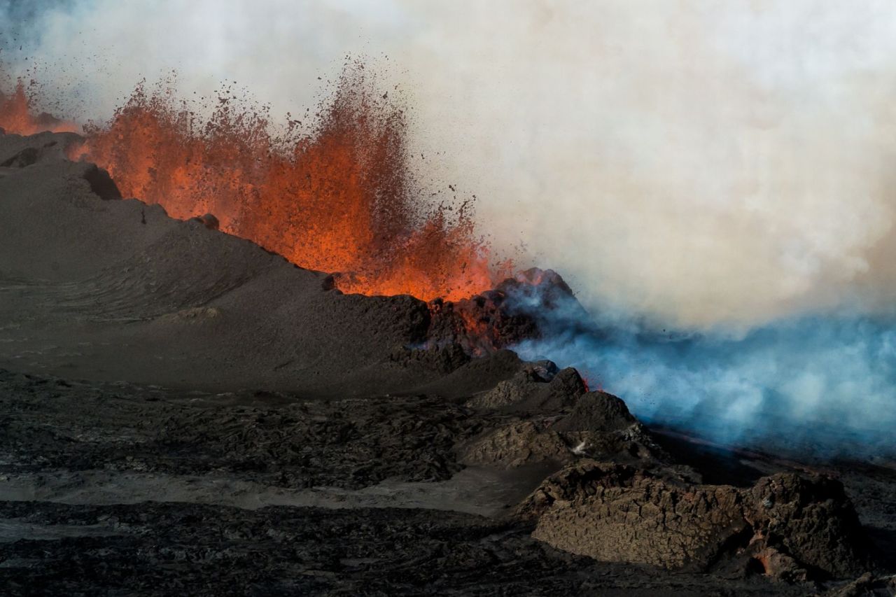
Lava Physics
Lava is rather fascinating as a fluid. Lava flow regimes range from extremely viscous creeping flows all the way to moderately turbulent channel flow. Lava itself also has a widely varying rheology, with its bulk properties like viscosity and its response to deformation changing strongly with temperature and composition. As lava cools, instabilities form in the fluid, causing the folding, coiling, branching, swirling, and fracturing associated with different types and classes of lava. (Image credit: E. Guddman, via Mirror)
The Physics of Sneezing
Sneezing can be a major factor in the spread of some illnesses. Not only does sneezing spew out a cloud of tiny pathogen-bearing droplets, but it also releases a warm, moist jet of air. Flows like this that combine both liquid and gas phases are called multiphase flows, and they can be a challenge to study because of the interactions between the phases. For example, the buoyancy of the air jet helps keep smaller droplets aloft, allowing them to travel further or even get picked up and spread by environmental systems. Researchers hope that studying the fluid dynamics and mathematics of these turbulent multiphase clouds will help predict and control the spread of pathogens. Check out the Bourouiba research group for more. (Video credit: Science Friday)

“Smoke”


Ethereal forms shift and swirl in photographer Thomas Herbich’s series “Smoke”. The cigarette smoke in the images is a buoyant plume. As it rises, the smoke is sheared and shaped by its passage through the ambient air. What begins as a laminar plume is quickly disturbed, rolling up into vortices shaped like the scroll on the end of a violin. The vortices are a precursor to the turbulence that follows, mixing the smoke and ambient air so effectively that the smoke diffuses into invisibility. To see the full series, see Herbich’s website. (Image credits: T. Herbich; via Colossal; submitted by @jchawner, @__pj, and Larry B)
P.S. – FYFD now has a page listing all entries by topic, which should make it easier for everyone to find specific topics of interest. Check it out!