This is the last week that my IndieGoGo project is open for donations. All money above and beyond what is needed for the conference will go toward FYFD-produced videos. Also, donors can get some awesome FYFD stickers.
As a reminder, those looking for more fluids–in video, textbook, or other form–can always check out my resources page. And if you know about great links that aren’t on there, let me know so that I can add them. On to the round-up!
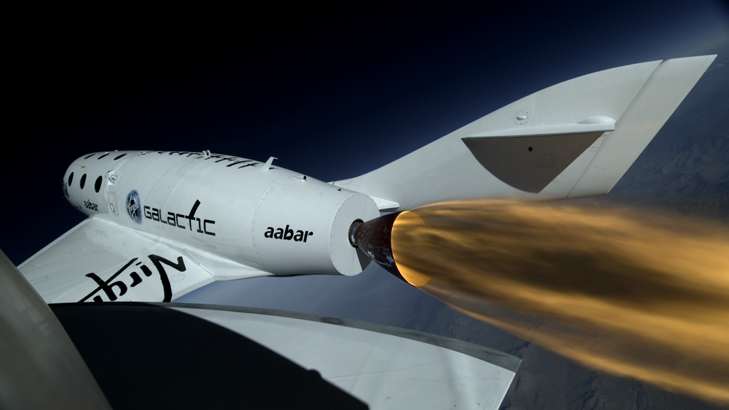
- Popular Science has look at what it was like to fly on the Concorde, the only supersonic commercial airliner ever flown.
- For the cyclists and CFD folks out there, Zipp has put out a new video discussing their Firecrest wheels’ aerodynamics.
- io9 explains how superhydrophobic surfaces impart a charge to water droplets and how this can be used to increase efficiency at power plants.
- BuzzFeed UK has 32 fun science GIFs, several of which are fluids-related, and several of which will look familiar to long-time readers. (via Flow Visualization on FB)
- Wired has an intriguing short on Acoustic Archives, a group that focuses on capturing the acoustic qualities of historic locations using custom-designed 3D microphones.
- Congratulations to Richard over at Flow Viz for hitting his 100th post! Here’s to many more.
- Finally, our lead image comes from Martin Klimas. Smithsonian’s blog has a feature on his work in which he transforms songs from artists like Pink Floyd, Daft Punk, and Bach into sonic sculptures using paint on speakers. (via Flow Visualization on FB)
I had a lot of fun earlier this week giving a talk for the Texas A&M Applied Mathematics Undergraduate Seminar series. I didn’t get a chance to record it, but the slides are up here if anyone is interested.
(Photo credit: M. Klimas)