Tag: supersonic wind tunnel

  • Featured Video Play Icon

    Why Compressed Air Cans Get Cold

    Anyone who’s used a can of compressed air to clean their computer or keyboard knows that the can quickly gets quite cold to the touch. This Minute Physics video explores some of the thermodynamics behind that process. Henry first identifies a few explanations that don’t quite line up with observations, before focusing in on the contents of the can: 1,1-difluoroethane. Inside the sealed can, this chemical sits in an equilibrium of part-liquid, part-vapor. But when pressure is released by opening the nozzle, the liquid boils, generating extra vapor and cooling whatever remains in the reservoir.

    Although it’s not a good explanation for the compressed air can’s cooling, the cooling of an expanding gas is very important in applications like supersonic wind tunnels. That first equation you see at 0:36 in the video (for isentropic adiabatic expansion) is key to what happens in a nozzle with supersonic flow. As the flow accelerates to supersonic speeds, its temperature drops dramatically. When I was in graduate school, we actually had to preheat our hypersonic wind tunnel (in pretty much the same way you would preheat your oven at home) before we ran at Mach 6 because otherwise the temperature inside the test section would drop so low that the oxygen would liquefy out of the air! (Image and video credit: Minute Physics)

  • Testing a Supersonic Car

    Testing a Supersonic Car

    How do you test a supersonic car like the Bloodhound SSC in a wind tunnel? With free-flying objects like airplanes, wind tunnel testing is relatively straightforward. Mounting a stationary model in a supersonic flow gives an equivalent flow-field to that object flying through still air at supersonic speeds. The same does not hold true for the supersonic car, though, because you need to account for the effect of the ground on airflow. One option is to build a moving wall in the wind tunnel. For low-speed applications, this is feasible but incredibly complicated and very expensive. For supersonic speeds, it’s impossible. You could achieve the same moving-wall effect at supersonic speeds with a rocket sled, but that is also expensive and difficult to fit in most experimental facilities. The simplest solution is the one you see above – build two models and mount them belly-to-belly. Reflecting the models makes the plane of symmetry a stagnation plane, which, fluid dynamically speaking, acts like an imaginary ground plane relative to the model. For more on the project and the technique, check out this article.  (Photo credit: B. Evans; via ThinkFLIP; submitted by G. Doig)

  • AEDC 16-ft Supersonic Tunnel

    AEDC 16-ft Supersonic Tunnel

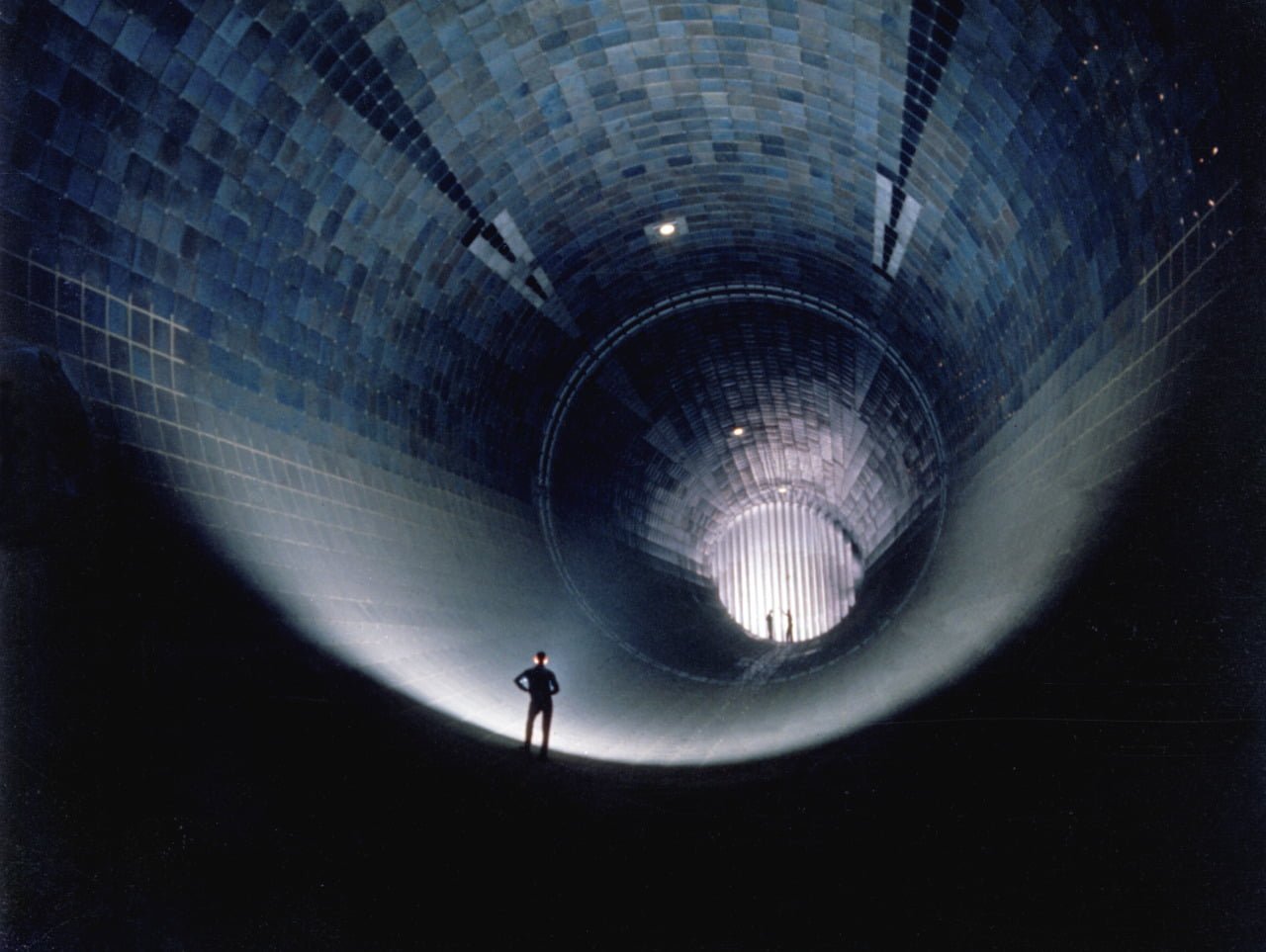
    This 1960 photo shows three men standing inside Arnold Engineering Development Complex’s 16-ft supersonic wind tunnel facility. The wind tunnel was capable of Mach numbers between 1.60 and 4.75 through a test section 4.8 meters wide and 20.2 meters long. It served as a large-scale testing facility for aircraft and propulsion systems. Like many large-scale and high-speed wind tunnel facilities in the United States, it is no longer active. In recent years, many unique wind tunnel facilities at NASA, military bases, and universities have been closed down, depriving researchers and engineers of the ability to include large-scale testing in their design and development of new technologies. These facility closures leave a substantial gap between the speeds and Reynolds numbers achievable in small-scale experiments and computational fluid dynamics and those experienced in flight. (Photo credit: P. Tarver)

  • Featured Video Play Icon

    Shock Trains

    In compressible flows, shock waves are singularities, a tiny distance across which the density, temperature, and pressure of a fluid change suddenly and discontinuously. In this video, there is a wedge at the top and bottom of the frame and a Pitot probe roughly in the center. Flow is left to right and is initially subsonic. Once Mach 6 flow is established in the wind tunnel, a series of shock waves and expansion fans appear as light and dark lines in this schlieren video. Oblique shocks extend from the sharp tip of each wedge and interfere to create a normal shock in front of the Pitot probe. The air that passes through the normal shock is subsonic to the right of the shock, whereas air that goes through the oblique shocks remains supersonic. The fainter lines further to the right are weaker shock waves and expansion fans that reflect off the walls and probe. They exist to continue turning the airflow around the probe and to equalize conditions between different regions. (Video credit: C. Mai et al.)

  • Supersonic Oil Flow Viz

    Supersonic Oil Flow Viz

    This image shows oil-flow visualization of a cylindrical roughness element on a flat plate in supersonic flow. The flow direction is from left to right. In this technique, a thin layer of high-viscosity oil is painted over the surface and dusted with green fluorescent powder. Once the supersonic tunnel is started, the model gets injected in the flow for a few seconds, then retracted. After the run, ultraviolet lighting illuminates the fluorescent powder, allowing researchers to see how air flowed over the surface. Image (a) shows the flat plate without roughness; there is relatively little variation in the oil distribution. Image (b) includes a 1-mm high, 4-mm wide cylinder. Note bow-shaped disruption upstream of the roughness and the lines of alternating light and dark areas that wrap around the roughness and stretch downstream. These lines form where oil has been moved from one region and concentrated in another, usually due to vortices in the roughness wake. Image © shows the same behavior amplified yet further by the 4-mm high, 4-mm wide cylinder that sticks up well beyond the edge of the boundary layer. Such images, combined with other methods of flow visualization, help scientists piece together the structures that form due to surface roughness and how these affect downstream flow on vehicles like the Orion capsule during atmospheric re-entry. (Photo credit: P. Danehy et al./NASA Langley #)

  • Featured Video Play Icon

    Starting a Rocket

    This computational fluid dynamics (CFD) simulation shows the start-up of a two-dimensional, ideal rocket nozzle. Starting a rocket engine or supersonic wind tunnel is more complicated than its subsonic counterpart because it’s necessary for a shockwave to pass completely through the engine (or tunnel), leaving supersonic flow in its wake. Here the situation is further complicated by turbulent boundary layers along the nozzle walls. (Video credit: B. Olson)