Tag: rheoscopic fluid

  • Featured Video Play Icon

    Peering Into the Gap

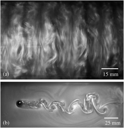
    This video offers a glimpse into turbulence developing in a classic flow set-up, a Taylor-Couette cylinder. The apparatus consists of two upright, concentric cylinders; the outer cylinder is fixed, and the inner one rotates. This video shows the gap between the cylinders, and it’s rotated so that the inner cylinder is at the bottom of the frame. Gravity points from left to right in the video. The fluid in the 8-cm gap between the cylinders is water, seeded with rheoscopic particles to visualize the flow.

    The video begins as the inner cylinder has just begun to rotate, dragging nearby fluid with it. A thin, laminar boundary layer forms at the bottom of the frame, growing as time goes on. A few seconds in, the boundary layer transitions to turbulence; look closely and you’ll see hairpin-shaped vortices appear. Just after that, the boundary layer becomes entirely turbulent and continues to slowly move upward to take over the full gap. The video is available in a full 4K resolution if you really want to get lost in the flow. (Video credit: D. van Gils)

  • Evaporative Convection

    Evaporative Convection

    Since we spend so much of our lives around transparent fluids like air and water, we often miss seeing some of their coolest-looking flows. Here, we see a layer of water only 3 centimeters deep but a full meter wide. It’s seeded with tiny crystals that reflect light depending on their orientation, which allows us to see the flow. Initially, the tank is spun up, then left stationary for 2 hours while evaporation cools the water.

    Normally, the resulting flow would be too slow to notice, but that’s where the magic of timelapse comes in. With it, we can see the wriggling dark lines marking areas where cool, dense water sinks and brighter regions where warm fluid rises. What begins as an array of polygonal convection cells quickly merges into a couple of large, rounded cells. Check out the full video below, where you can see the streaming patterns far better than in animation. (Image and video credit: UCLA Spinlab)

  • Vortex Dome

    Vortex Dome

    Are you staring into the eye of a hurricane or watching the spin of a simple desk toy? Part of the beauty of fluid dynamics is recognizing how similar they both are. This is high-speed footage of a toy known as a “Vortex Dome,” which contains a fluid filled with tiny mica particles that react to local forces and allow users to “see” the flow. Before the video begins, the toy has been spinning for long enough that the fluid inside rotates as if it were a solid body. Then an unseen hand sets the disk spinning in the opposite direction and we observe what happens.

    Fluid at the outer edge of the toy has to immediately change direction due to friction with the wall. That change in momentum slowly passes from the wall inward as viscosity between one layer of fluid to the next passes that signal. This creates the rolls we see in the first animation. Initially, those rolls are smooth, but they quickly roughen as disturbances in them grow into full-blown turbulence. Meanwhile, viscosity continues to pass the change in rotation inward, ultimately swallowing the entire interior of the toy. Left spinning indefinitely, the disturbances will eventually quiet out and the entire fluid will spin as one. (Image and video credit: D. van Gils)

  • Replacing Kalliroscope

    Replacing Kalliroscope

    Although you may not recognize the name, you’ve probably seen Kalliroscope (top image), a pearlescent fluid that creates beautiful flow patterns when swirled. This rheoscopic fluid was invented in the mid-1960s by artist Paul Matisse and, over the following decades, became a staple of flow visualization techniques. Kalliroscope contained a suspension of crystalline guanine. Since the crystals were asymmetric, they would orient themselves depending on the flow and, from there, scatter light, creating the beautiful pearlescent effect seen above.

    Unfortunately for researchers, the production of guanine crystals was expensive and difficult. The cosmetics industry was their main consumer and over time, they moved toward mica and other cheaper mineral alternatives. The company that produced Kalliroscope gave up production in 2014, leaving researchers scrambling for a suitable alternative.

    One contender for a new standard rheoscopic fluid is based on shaving cream. By diluting shaving cream 20:1 with water, researchers are able to extract stearic acid crystals, which form an admirable alternative to Kalliroscope (middle collage). Like Kalliroscope, the resulting fluid is pearlescent and reveals flow features well (bottom two images). Stearic acid crystals are also closer in density to water than guanine, so the fluid remains in suspension far better than Kalliroscope. Plus, the best shaving cream is cheap and widely available, meaning that this is a DIY project just about anyone can do! (Image credits: Kalliroscope – P. Matisse; other images – D. Borrero-Echeverry et al.; research credit: D. Borrero-Echeverry et al.)

  • Rheoscopic Flow Vis

    Rheoscopic Flow Vis

    One of the great challenges in visualizing fluid flows is the freedom of movement. A fluid particle – meaning some tiny little bit of fluid we want to follow – is generally free to move in any direction and even change its shape (but not mass). This makes tracking all of those changes difficult, and it’s part of why there are so many different techniques for flow visualization. The technique an experimenter uses depends on the information they hope to get.

    Often a researcher may want to know about fluid velocity in two or more directions, which can require multiple camera angles and more than one laser sheet illuminating the flow. An alternative to such a set-up is shown above. The injected fluid – known as a rheoscopic fluid – contains microscopic reflective particles, in this case mica, that are asymmetric in shape. Imagine a tiny rod, for example. By illuminating the rod from different directions with different colors of light, you can determine the particle’s orientation based on the color it reflects. Since the orientation of the particle depends on the surrounding flow, you can infer how the flow moves. (Image credit and submission: J. C. Straccia; research link: V. Bezuglyy et al.)